SIPLACE-SX4-DX4-用户手册.pdf - 第183页
Service Work 3.11.1 Replacing the Fixed/Gu ide Castors [00341918-xx] X-Series Component Trolley Service Manual SIPLACE SX4/DX4 183 3.11 3 . 1 1 X - S e r ie s C o m p o n e n t T r o lle y X-Series Component Trolley 3.11…
Service Work
COT insert 3.10.9 Replacing the Feed Control [03082077-xx]
182 Service Manual SIPLACE SX4/DX4
3.10.9
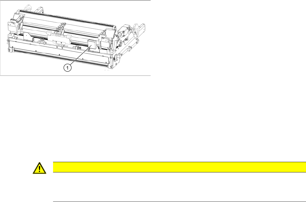
3.10.9 Replacing the Feed Control [03082077-xx]
Replacing the Feed Control [03082077-xx]
Parts, equipment and tools
▪ Insert control assembly SX4 [03082077-xx]
Overview
Removal
► Switch off the machine and secure it to prevent unauthorized reactivation. Observe the instructions
in section "1.2 Preparatory Work..." [ ➙ 12].
► Dismantle the nozzle changer over the feed control. (See "3.8.1 Replacing the Nozzle Changer"
[ ➙ 152])
► To gain better access, you may need to disconnect the COT insert and pull it slightly out of the ma-
chine. Observe the instructions in section Installation Position for COT Insert (Table Positions).
Alternatively, you can improve access by removing the upper section of the component camera.
► Unplug all electrical connections to the insert control. You may want to mark their positions, to make
clear assignment easier later on.
► Loosen the screws fastening the insert control and remove the insert control from the machine.
Installation
► Follow the removal instructions in reverse order for installation.
See also
3.10.1 Replacing the COT Insert Assembly [03080552-xx] [ ➙ 170]
1. Insert control
CAUTION
Component Camera
► The component camera mirror has sharp edges.
► Take care not to damage the component camera.
Service Work
3.11.1 Replacing the Fixed/Guide Castors [00341918-xx] X-Series Component Trolley
Service Manual SIPLACE SX4/DX4 183
3.11
3.11 X-Series Component Trolley
X-Series Component Trolley
3.11.1
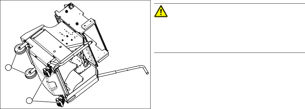
3.11.1 Replacing the Fixed/Guide Castors [00341918-xx]
Replacing the Fixed/Guide Castors [00341918-xx]
Parts, equipment and tools
▪ Fixed castor [00341918-xx] or
Guide castor [03004958-xx]
▪ Second person
Removal/Installation
CAUTION!
Heavy machine part!
The component trolley must be placed on one side in or-
der to remove the fixed/guide castors. You will need two
people to perform this task.
► Move the component trolley out of the machine.
► Place the component trolley on its side, on a suitable
surface.
► Loosen the fastening screw on the fixed (1) or guide
castor (2) to be replaced.
► Insert the new fixed or guide castor.
► Stand the component trolley on its wheels again.
1
2
Service Work
X-Series Component Trolley 3.11.2 Replacing the Locking Latch [03069205-xx]
184 Service Manual SIPLACE SX4/DX4
3.11.2
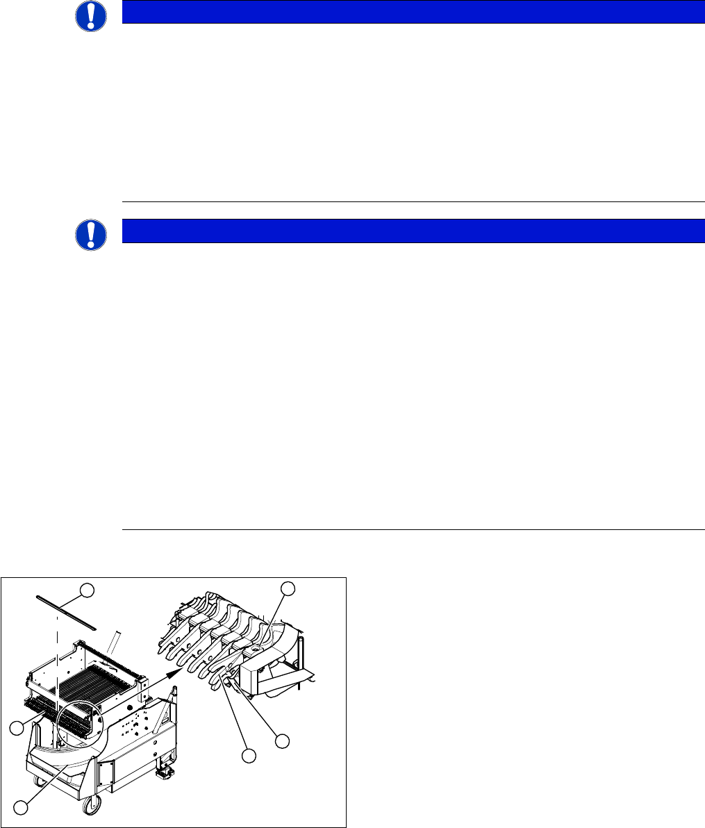
3.11.2 Replacing the Locking Latch [03069205-xx]
Replacing the Locking Latch [03069205-xx]
Parts, equipment and tools
▪ Single locking latch [03069205-xx]
▪ Tension spring [03010352-xx]
▪ Cover plate for locking strip [03077142-xx]
SXDX4 SX DX12V1 – M anual Table and DX Trolley
Overview
NOTICE
Component trolley X/SX series
Component trolleys from the X series (S) and SX series require a locking latch for each feeder
track.
► X series (S), SX4: feeder lock [03023777-xx] with 40 locking latches
(1x per component trolley X series (S)/SX4)
► Feeder lock [03057284-xx] with 30 locking latches
(1x per 30 track, 2x per 60 track component trolley SX1/SX2)
⇨ The feeder lock can also be completely dismantled from the component trolley and re-
placed.
NOTICE
Manual table, component trolley DX
When using a manual table or component trolley for the DX series, only every second feeder
track is locked.
If too many locking latches are fitted or if they are fitted in the wrong places, these will not be
unlocked by the unlocking device and you will not be able to remove the feeder modules. In this
case, use the unlocking hook [03038882-xx]. (See "3.13.6.1 Operating the Unlocking Hook"
[ ➙ 208])
► Feeder lock 40 [03082778-xx] with 20 locking latches
(1x per component trolley DX4)
► Feeder lock 30/2 fold [03081586-xx] with 17 locking latches
(1x 30 track and 2x 60 track manual table or component trolley DX1/DX2)
⇨ The feeder lock can also be completely dismantled from the component trolley and re-
placed.
⇨ Please also observe section "3.13.5 Replacing the Feeder Lock on the Manual Table
[03082778-xx]" [ ➙ 204].
1. Waste tape container
2. Cover
3. Position of complete feeder locking mechanism
4. Locking latch
5. Tension spring
6. Pressure plate
4
6
5
1
3
2