SIPLACE-SX4-DX4-用户手册.pdf - 第105页
Service Work 3.6.5 Replacing the Lifting Table Motor [03064983- xx] (EC only) Conveyor Service Manual SIPLACE SX4/DX4 105 Installation ► Follow the removal in structions in reverse order for installati o n. Also observe …
Service Work
Conveyor 3.6.5 Replacing the Lifting Table Motor [03064983-xx] (EC only)
104 Service Manual SIPLACE SX4/DX4
3.6.5
3.6.5 Replacing the Lifting Table Motor [03064983-xx] (EC only)
Replacing the Lifting Table Motor [03064983-xx] (EC only)
Parts, equipment and tools
▪ BLDC (brushless DC) motor with PLG (planetary gear) and brake [03064983-xx]
Removal
CAUTION
Only on the single conveyor!
The lifting table motor may only be replaced on single conveyors.
The lifting table motor may not be replaced on dual or quad lane conveyors. In these cases,
you may need to replace the entire lifting table.
CAUTION
Do not loosen the lifting table mechanism
The lifting table mechanism has been factory fitted with adjustment shims. Do not remove
these.
The only exception is the lifting table motor on the single conveyor.
NOTICE
Lifting table plate fixtures
► Mark the positions of the lifting table plate fixtures.
If these are still mistakenly exchanged, you will need to reset the parallelism of the lifting
table plates after installation.
► Remove the lifting table from the machine. (See
"3.6.4 Replacing the Lifting Table Unit" [ ➙ 101])
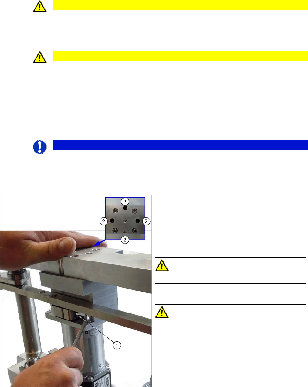
► Unplug the connection between the motor and the
rods (1).
► Loosen the screws (2) fastening the motor. Some of
these are only accessible if you move the rods up-
wards (thereby turning the gear shaft by 90 degrees).
CAUTION!
Make sure that you do not loosen the other four screws!
► Remove the motor.
CAUTION!
There are several shims on the gear shaft. These need to
be taken over to the new motor and fitted there in the
same positions and quantities.

Service Work
3.6.5 Replacing the Lifting Table Motor [03064983-xx] (EC only) Conveyor
Service Manual SIPLACE SX4/DX4 105
Installation
► Follow the removal instructions in reverse order for installation. Also observe the following instruc-
tions:
CAUTION
Installation instructions
► Fit the shims onto the new motor.
► Make sure that the motor connection cables do not rub against any parts. In particular,
make sure that they do not point upwards or downwards.
► Perform a reference run for the lifting table motor. (See also "5.5.4 Calibrating the Motors
in the SX Conveyor" [ ➙ 260])
Service Work
Conveyor 3.6.6 Replacing the Cylinder Unit on the Adjustment Unit (DC/QC only)
106 Service Manual SIPLACE SX4/DX4
3.6.6
3.6.6 Replacing the Cylinder Unit on the Adjustment Unit (DC/QC only)
Replacing the Cylinder Unit on the Adjustment Unit (DC/QC only)
Parts, equipment and tools
There are two versions of the cylinder unit, one for the adjustment unit in the input area or center and
one for the adjustment unit in the output area.
▪ Adjustment unit 1 for width adjustment DC split (incl. trailing cable) – input area/center [03081359-xx]
▪ Adjustment unit 2 for width adjustment DC split (incl. trailing cable) – output area [03081361-xx]
Overview
Removal
► Use the software to move the conveyor sides into the position which allows you best access.
► If required, loosen the conveyor side clamps. (see "3.6.1 Loosening the Conveyor Side Clamps"
[➙95]).
► Switch off the machine, disconnect it from the power supply and secure it to prevent unauthorized
reactivation. Observe the instructions in section "1.2 Preparatory Work..." [ ➙ 12].
► Loosen the screws fastening the lifting table plate and remove the lifting table plate.
► Dismantle the cover plate on the lower end of the trailing cable, to gain access to the cable.
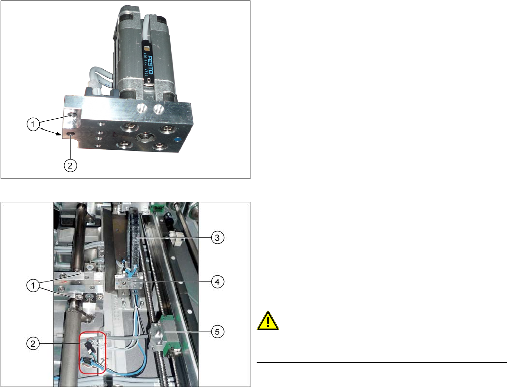
Cylinder unit
1. Holes for the carriage fastening screws
2. Centering hole
1. Lifting tables
2. Electrical and pneumatic connections for the cylinder
unit
3. Trailing cable for the cylinder unit
4. Cylinder unit
5. Guide carriage with receptacle for cylinder unit and
centering pin
CAUTION!
Never dismantle the carriage or the receptacle for the cyl-
inder unit!