SIPLACE-SX4-DX4-用户手册.pdf - 第200页
Service Work Manual Table (DX4) 3.13.1 Replacing the Guide Profile (Omega Profile) 200 Service Manual SIPLACE SX4/DX4 3.13 3 . 1 3 M a n u a l T a b le ( D X 4 ) Manual Table (DX4) 3.13.1 3 . 1 3 . 1 R e p la c in g t h …
Service Work
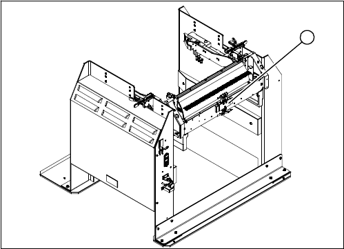
3.12.10 Replacing the Control Valve [03003489-xx] Docking Station for X-Series Component Trolley
Service Manual SIPLACE SX4/DX4 199
3.12.10
3.12.10 Replacing the Control Valve [03003489-xx]
Replacing the Control Valve [03003489-xx]
Parts, Equipment and Tools
▪ Control valve [03003489-xx]
Removal/Installation
► Unplug the electricity and compressed air cables
from the control valve (1).
► Loosen the fastening screws and remove the control
valve.
► Install the new control valve.
► Reconnect to the electrical and compressed air sys-
tems.
1
Service Work
Manual Table (DX4) 3.13.1 Replacing the Guide Profile (Omega Profile)
200 Service Manual SIPLACE SX4/DX4
3.13
3.13 Manual Table (DX4)
Manual Table (DX4)
3.13.1
3.13.1 Replacing the Guide Profile (Omega Profile)
Replacing the Guide Profile (Omega Profile)
Parts, equipment and tools
▪ Guide profile on front section: guide profile L=150 mm [03081674-xx]
▪ Guide profile on back section: guide profile L=280 mm [03084321-xx]
Overview
Removal
► Loosen the screws fastening the guide profile on the underside of the table.
► Remove the guide profile.
Installation
► Follow the removal instructions in reverse order for installation. Also observe the following instruc-
tions:
CAUTION
Back part, dummy feeder
Do not operate the machine without the back part of the manual table or without the dummy
feeder.
NOTICE
Always replace together
We recommend that you always replace the guide profiles which belong together (on the front
and back parts) at the same time.
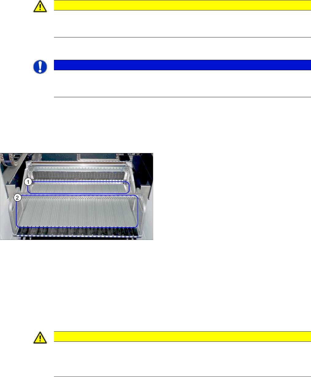
Guide profiles (using example of DX1/DX2)
1. Guide profiles on the front section
2. Guide profiles on the back section
CAUTION
Installation instructions
► To correctly align the guide profiles from the front to the back part (removable), we recom-
mend proceeding as follows:
Place a feeder to the left and right of the guide profile and then screw the guide profiles tight.
Service Work
3.13.2 Removing the Back Section of the Manual Table Manual Table (DX4)
Service Manual SIPLACE SX4/DX4 201
3.13.2
3.13.2 Removing the Back Section of the Manual Table
Removing the Back Section of the Manual Table
Parts, equipment and tools
Select the correct spare part:
▪ Rubber mallet
Overview
Removal
► Loosen the two screws fastening the back section.
► Pull the back section out of the pins and remove it. You may need to use a rubber mallet to help you.
Installation
► Follow the removal instructions in reverse order for installation.
CAUTION
Back part, dummy feeder
Do not operate the machine without the back part of the manual table or without the dummy
feeder.
Machine type Designation Item No.
DX4 Table module MT 40 03082703-xx
DX1/DX2 Table module MT 60 03081585-xx
Table module MT 30 03082639-xx
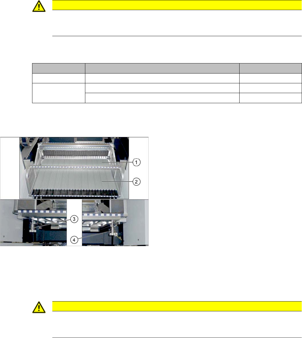
Manual table (using example of DX1/DX2)
1. Front part
2. Back part
3. Screw fastening the back section, left
4. Screw fastening the back section, right
CAUTION
Do not lift by holding on to the centering bar.
► Only use the handles provided to lift the back section. The fixture bar is used to stabilize
and position the feeders. Take care not to bend it.