SIPLACE-SX4-DX4-用户手册.pdf - 第126页
Service Work Conveyor 3.6.20 Replacing the Stopper [03084034-xx] 126 Service Manual SIPLACE SX4/DX4 Installation ► Follow the removal in structions in reverse order for installati o n. Also observe the following instruc …
Service Work
3.6.20 Replacing the Stopper [03084034-xx] Conveyor
Service Manual SIPLACE SX4/DX4 125
3.6.20
3.6.20 Replacing the Stopper [03084034-xx]
Replacing the Stopper [03084034-xx]
Parts, equipment and tools
▪ Stopper 25 SX pneumatic assembly [03084034-xx]
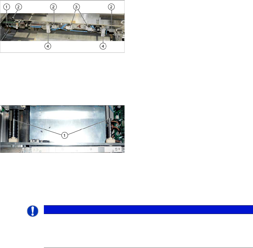
Overview
Removal
► Use the software to move the conveyor sides into the position which allows you best access. As an
alternative, you can loosen the clamps for the relevant sides in dual conveyors.
► Switch off the machine, disconnect it from the power supply and secure it to prevent unauthorized
reactivation. Observe the instructions in section "1.2 Preparatory Work..." [ ➙ 12].
► Dismantle the cover plate on the sensor rail.
► Unplug the pneumatic connections to the stopper. You may want to mark the positions, to make clear
assignment easier later on.
► Loosen the two screws fastening the stopper and remove the stopper. Make sure that you do not
lose the angle plate. You may want to mark the position of the screws and plate, to make clear as-
signment easier later on.
1. Conversion board
2. Ultrasonic sensors (3x)
3. Solenoid valves (2x)
4. Stoppers (2x PA1, 3x PA2)
► If needed, the sensor rail can be removed to allow
better access. Simply loosen the two screws (1) on
the ends of both shafts.
NOTICE
Angle plate
The angle plate fitted between the stopper and sensor rail serves as a support plate in case a
long board (> 280 mm) moves backwards against the stopper. The angle plate is also used to
set the distance of the stoppers to one another. The angle plate can therefore have different
thicknesses and care should be taken not to confuse the individual angle plates.

Service Work
Conveyor 3.6.20 Replacing the Stopper [03084034-xx]
126 Service Manual SIPLACE SX4/DX4
Installation
► Follow the removal instructions in reverse order for installation. Also observe the following instruc-
tions:
See also
3.6.1 Loosening the Conveyor Side Clamps [ ➙ 95]
CAUTION
Installation instructions
► Make sure that the cable is run correctly and does not rub against any parts.
► During fitting, make sure that the angle plate is flush against the side of the sensor rail base
unit.
► Make sure that the distance between the stoppers is correct: 304+/-0.5 mm.
Service Work
3.6.21 Replacing the Ultrasonic Sensor PXS240 [03069863-xx] Conveyor
Service Manual SIPLACE SX4/DX4 127
3.6.21
3.6.21 Replacing the Ultrasonic Sensor PXS240 [03069863-xx]
Replacing the Ultrasonic Sensor PXS240 [03069863-xx]
All ultrasonic sensors used can be disconnected for replacement and dismantled.
Parts, equipment and tools
▪ Programming cable for PXS240 [03073330-xx]
▪ Sonar sensor UB100-F77 [03089004Sxx] (compatible)
Incl. 2x "Press-in thread insert M2" [03088352-xx]
(replaces: old: sonar sensor PXS240 [03069863-xx])
▪ Setting gauge for ultrasonic sensors [03076989-xx]
▪ Loctite 401 [00805104-xx], if required
Overview
1. Conversion board
2. Ultrasonic sensors (3x)
Access to the ultrasonic sensors depends on the in-
stallation position. If the sensors are not directly ac-
cessible, you may need to remove the conversion
board.
3. Solenoid valves (2x)
4. Stoppers (2x)
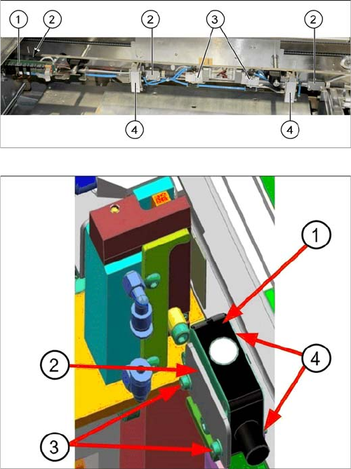
Sonar sensor on the stopper positions:
1. Sonar sensor
2. Sensor rail fixture bracket
3. Fastening screws ISO4762–M2x16-A2-70
[03042529-xx] with washers DIN125-A2.2-140HV-A2
[00301541-xx].
4. Press-in nut