SIPLACE-SX4-DX4-用户手册.pdf - 第81页
Service Work 3.5.5 Replacing the Trailing Cable Gantries Service Manual SIPLACE SX4/DX4 81 Overview See also 3.5.5.2.3 Preparing th e Trailing Cable [ ➙ 79] 3.5.5.1.1 Handling the Hose Unlocking Tool [03047090-xx…
Service Work
Gantries 3.5.5 Replacing the Trailing Cable
80 Service Manual SIPLACE SX4/DX4
► Mark the pneumatic hoses through the holes (4) in the gauge. Observe the position labeled X hose.
► Use the hose pliers to cut the pneumatic hoses at the marked position. The pneumatic hoses can
now be run inside the pneumatic distributor, with the correct curvature.
► Observe the designation for the respective gantry on the gauge (1) (gantry 1+3 or gantry 2+4). Se-
lect the correct gauge.
► Place the stopper edge (2) of the gauge (see mark labeled edge for clamp X +Y on the gauge) at the
edge of the clamp for the Y axis.
► Mark the pneumatic hoses through the holes (3) in the gauge.
► Use the hose pliers to cut the pneumatic hoses at the marked position. The pneumatic hoses should
now have the correct length and can be connected to the severed pneumatic hoses in the machine
base.
CAUTION
Mark the correct position!
► Observe the position labeled X hose.
► Observe the position marked machine inside on the gauge.
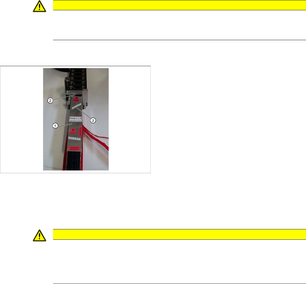
Shortening the Y hoses to the pneumatic distributor in the
machine base
1. Gauge for shortening the hoses
2. Stopper edge at the machine base clamp
3. Hose marking
CAUTION
Mark the correct position!
► Observe the position labeled Y hose.
► To ensure that they have the correct length, cut the pneumatic hoses at the marking labeled
"Y hose". If the pneumatic hoses are cut too short, you will have to discard the entire trailing
cable.
Service Work
3.5.5 Replacing the Trailing Cable Gantries
Service Manual SIPLACE SX4/DX4 81
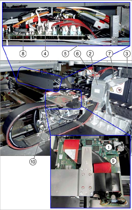
Overview
See also
3.5.5.2.3 Preparing the Trailing Cable [ ➙ 79]
3.5.5.1.1 Handling the Hose Unlocking Tool [03047090-xx] [ ➙ 78]
1. Vision board spread spectrum (VBSX) assembly
[03067289-xx]
This board is located at the top of the head interface.
2. Trailing cable console
3. Power track chain
4. Trailing interface for gantry
Gantry 2 and 4 [03071356-xx]
Gantry 1 and 3 [03071355-xx]
5. Pneumatic hoses to the pneumatic distributor (in the
machine base)
6. Gantry interface
Gantry 2 and 4 [03059909-xx]
Gantry 1 and 3 [03059908-xx]
7. Connection piece for cooling tubes to Y motor
8. Vision hotlink adapter VHA [03050555-xx]
9. MODULE/Head interface
C700X-L [03055068-xx]
C700X-R [03055070-xx]
10. Pneumatic distributor
Service Work
Gantries 3.5.5 Replacing the Trailing Cable
82 Service Manual SIPLACE SX4/DX4
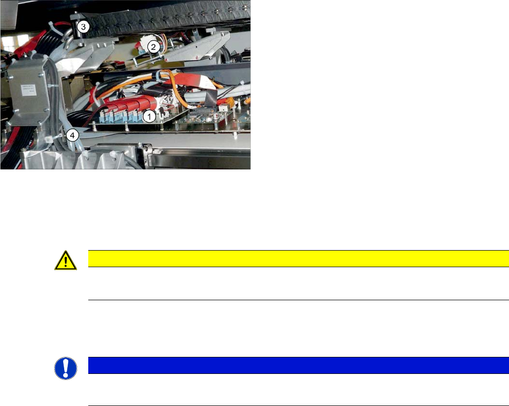
Removal
► Disconnect the cooling tubes (4) from the Y motor.
► Loosen the flat ribbon cable on the trailing cable interface gantry (1). Take care not to lose the brack-
ets for the press-fit connections. They could fall out and be lost.
► Remove cable ties where necessary.
► Remove the necessary cable ties at the gantry interface (4) and disconnect the flat ribbon cable.
► Disconnect the motor, proximity switches, incremental encoder and temperature sensor cables from
the gantry interface (4).
1. Trailing interface for gantry
Gantry 2 and 4 [03071356-xx]
Gantry 1 and 3 [03071355-xx]
2. Gantry interface
Gantry 2 and 4 [03059909-xx]
Gantry 1 and 3 [03059908-xx]
3. Mount for trailing cable
4. Cooling tubes
CAUTION
Note the order in which the terminal connections are arranged.
► Label the press-fit connections to the flat ribbon cables, for easier reconnection later.
NOTICE
Refitting the gantry interface board.
The gantry interface board is installed on the mount of the new trailing cable.