SIPLACE-SX4-DX4-用户手册.pdf - 第261页
Settings 5.5.5 Board Clamping Conveyor Settings Service Manual SIPLACE SX4/DX4 261 5.5.5 5 . 5 . 5 B o a r d C la m p in g Board Clamping 5.5.5.1 5 . 5 . 5 . 1 S e t t in g t h e B o a r d C la m p in g ( A c t u a t o r…
Settings
Conveyor Settings 5.5.4 Calibrating the Motors in the SX Conveyor
260 Service Manual SIPLACE SX4/DX4
5.5.4
5.5.4 Calibrating the Motors in the SX Conveyor
Calibrating the Motors in the SX Conveyor
If the motors for the automatic width adjustment or for the lifting tables are replaced in SIPLACE SX ma-
chines, they need to be calibrated via the software afterwards. This is necessary since each motor has
a different zero point and calibration is the only way to enter the correct zero point into the machine data.
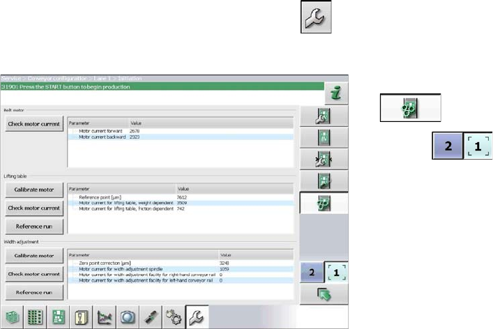
Calibration
► Start up the station.
► Switch over to the activity level Machine Service (or better still)
► Switch over to the service menu .
► Select the Conveyor configuration button.
► Select the Initiate conveyor parameters
button.
► Use the button to select the required con-
veyor lane.
► Calibrate the relevant motor by either clicking the
"Width adjustment" or "Motor calibration" button in
the Lifting table section.
Settings
5.5.5 Board Clamping Conveyor Settings
Service Manual SIPLACE SX4/DX4 261
5.5.5
5.5.5 Board Clamping
Board Clamping
5.5.5.1
5.5.5.1 Setting the Board Clamping (Actuator)
Setting the Board Clamping (Actuator)
If the conveyor control issues the error Clamping error conveyor, you need to check the distance from
the lifting table actuator to the upper edge of the conveyor belt.
Parts, equipment and tools
▪ Setting Gauge for Actuator [03049740-xx]
▪ Terminal strip [03076699-xx]
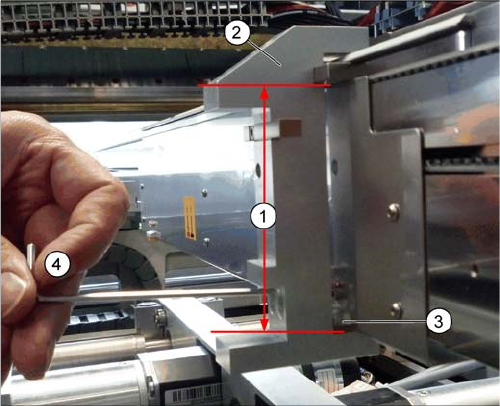
Setting
► Fit the terminal strip onto the long side of the setting gauge.
► Loosen the screws fastening the actuator.
► Attach the setting gauge to the conveyor side, as shown in the diagram.
► Tighten the screws fastening the actuator. This sets the distance to 94.0 mm.
► Repeat this setting at all actuators.
Setting the board clamping (using example of SX1/SX2)
1. Distance of 94.0 mm from the lower edge of the actu-
ator to the upper edge of the conveyor toothed belt
2. Setting gauge
3. Actuator
4. Loosen and tighten the screws fastening the actuator
through the hole provided in the gauge.
Settings
Conveyor Settings 5.5.6 Lifting Table
262 Service Manual SIPLACE SX4/DX4
5.5.6
5.5.6 Lifting Table
Lifting Table
5.5.6.1
5.5.6.1 Setting the Parallelism and Height of the Lifting Table Plate
Setting the Parallelism and Height of the Lifting Table Plate
Overview
Setting
► Use the software to move the conveyor sides to maximum width. (see also "3.6.1 Loosening the Con-
veyor Side Clamps" [ ➙ 95]).
► Loosen the screws fastening the lifting table plate (countersunk screws) but do not remove the lifting
table plate.
► Use the software to clamp the lifting table (without board).
► Underneath the fastening screws, there are setting screws (socket-head 5).
Use these setting screws to set the lifting table plate so that it has no play between it and the clamp-
ing edge.
► Check all four corners of the lifting table for any play.
► Check the setting by clamping a board into place. Check all corners to see whether there is any play.
► Calibrate the zero position of the lifting table motor.
See also
1.2 Preparatory Work... [ ➙ 12]
DANGER
Press the EMERGENCY STOP!
Before performing adjustment work you must ensure that the lifting table has been secured
against movement!
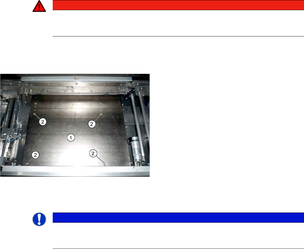
Lifting table plate (example of X-Series S shown)
1. Lifting table plate
2. Fastening screws for lifting table plate
NOTICE
Single, dual conveyor
The setting is shown in the diagram using the example of a lifting table unit for the dual conveyor
(DC). Setting the single conveyor (SC) follows the same procedure.