SIPLACE-SX4-DX4-用户手册.pdf - 第163页
Service Work 3.9.7 Replacing the Cutter Blades Cutter Service Manual SIPLACE SX4/DX4 163 3.9.7 3 . 9 . 7 R e p la c in g t h e C u t t e r B la d e s Replacing the Cutter Blades Parts, equipment and tools Select the righ…
Service Work
Cutter 3.9.6 Replacing the Proximity Switch [03063590]
162 Service Manual SIPLACE SX4/DX4
3.9.6
3.9.6 Replacing the Proximity Switch [03063590]
Replacing the Proximity Switch [03063590]
Parts, equipment and tools
▪ Proximity switch with cable (incl. four signal transmitters) [03063590-xx]
Overview
Removal/installation
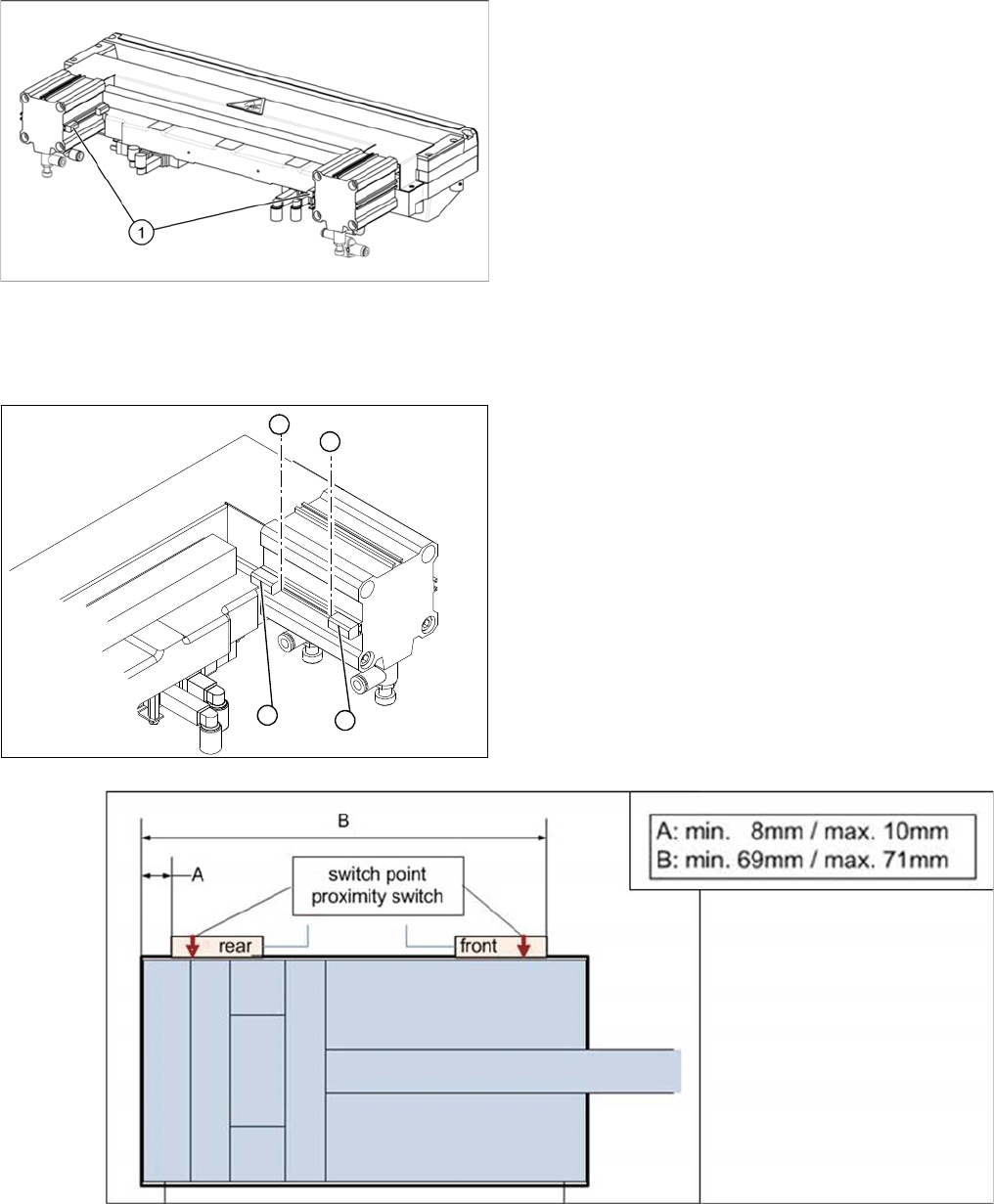
Cutter (using example of X series)
1. Two proximity switches on each short-stroke cylinder
► To make subsequent checking easier, use a perma-
nent marker to mark the exact installation position (3)
of the proximity switch (1) or (2) on the short-stroke
cylinder.
► Loosen the screw fastening the proximity switch to
the short-stroke cylinder.
► Unplug the connection cable.
► Fit the proximity switch at the positions shown in the
following diagram. These should match the positions
marked (3).
► Secure the fastening screws with locking varnish.
► Reconnect to the electricity supply.
► Check the switching points of the proximity switches.
1
2
3
3

Service Work
3.9.7 Replacing the Cutter Blades Cutter
Service Manual SIPLACE SX4/DX4 163
3.9.7
3.9.7 Replacing the Cutter Blades
Replacing the Cutter Blades
Parts, equipment and tools
Select the right set of blades.
We recommend the following additional spare parts:
▪ 2x blade cover (cutter HF) [03000553-xx] (cover for screws of movable blades)
▪ 2x ISO4762-M5x35-12.9, geomet 321+VL [03057290-xx] (screws for movable blades)
▪ 2x articulated joint (cutter HF) [03000518-xx]
▪ 2x DIN71412-BM6 [03036943-xx] (lubrication nipple)
Consumables required:
▪ Lubricant grease Klüber BEM 34-132 tin 1 kg [00374565-xx] (identical to the lubricant grease used
on the guide carriage of the gantry)
▪ Interflon Fin Grease [03020782-xx]
▪ LOCTITE 243 screw locking varnish [00334892-xx]
Tools required
▪ Extra protection gloves, leather [00091001-xx]
▪ Torx screwdriver ESD 1.0-5.0 Nm [03078400-xx]
▪ Torque wrench 2.5 - 25 Nm [00376625-xx]
▪ Bit holder for TorqueVario screwdriver [03078706-xx]
▪ Socket-head bit size 3-6
▪ Fork wrench, size 10
▪ Feeler gauge
▪ Brush
▪ Cloth
▪ Two large parallel clamps and a sturdy table with even surface, to clamp down the dismantled cutter
CAUTION
Risk of injury!
There is a high risk of injury from the blades and the tape deflector.
► Wear appropriately thick protective gloves!
► Never reach into the cutter from below or into the empty-tape duct from above.
► Make sure that no-one can injure themselves on the cutter after it has been dismantled and
placed next to the machine!
NOTICE
Turn the blade
The fixed and movable blades have been sharpened on both sides. If one side becomes blunt,
you can rotate the blade by 180 degrees to use the other side.
Machine Tape cutter, pneumatic Function status Set of blades
X series, SX4, DX4, X
series S
03066690-xx(without CAN nodes) -01 03009259-xx
HF, X series 03000487-xx -01 to -03 03000501-xx
-04 to -05 03009259-xx
X Series 03019941-xx(with control unit) -01 03009259-xx
03052900-xx(with CAN nodes) -01 to -02 03009259-xx
Service Work
Cutter 3.9.7 Replacing the Cutter Blades
164 Service Manual SIPLACE SX4/DX4
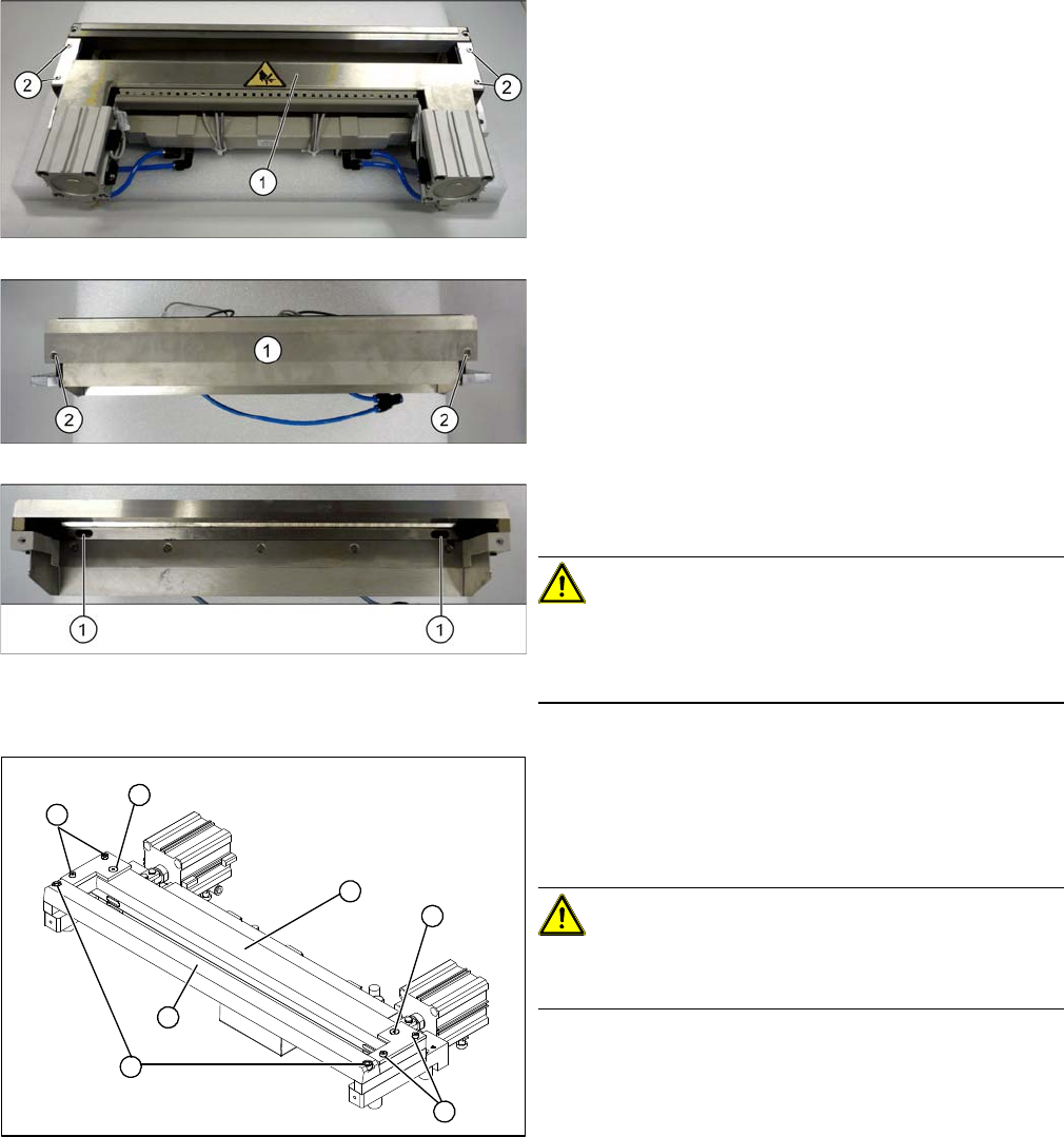
Removal
► Remove the cutter from the machine. (See "3.9.1 Re-
placing the Cutter on the COT Insert [03066690-xx]"
[ ➙ 154])
► Loosen the screws (2) fastening the top cover
plate (3) and then remove the cover plate.
► Loosen the screws (2) fastening the baffle plate (3) to
the back of the cutter and remove the baffle plate.
► Remove the caps over the fastening screws (1) on
the movable blade and loosen the blade.
CAUTION!
Risk of injury!
There is a risk of injuring yourself on the cutting edge of
the blades.
Cutter (using example of X series)
► Loosen and remove the two screws (1) fastening the
stationary blade (2).
► Loosen the screws fastening the left and right tape
deflectors (3) above the moveable blade.
CAUTION!
Do not loosen all screws!
Do not loosen these two screws (4)
► Remove the tape deflector holder with the tape de-
flector (5) and carefully place the whole unit down
(with the tape deflector facing upwards).
4
3
5
1
4
3
2