SIPLACE-SX4-DX4-用户手册.pdf - 第29页
Overview of the Modules 2.9.4 Width Adjustment X-Series component trolley Service Manual SIPLACE SX4/DX4 29 2.11 2 . 1 1 X - S e r ie s c o m p o n e n t t r o lle y X-Series component trolley See also 3.11 X-Serie s…
Overview of the Modules
COT Insert for SX4 2.9.4 Width Adjustment
28 Service Manual SIPLACE SX4/DX4
2.9.4
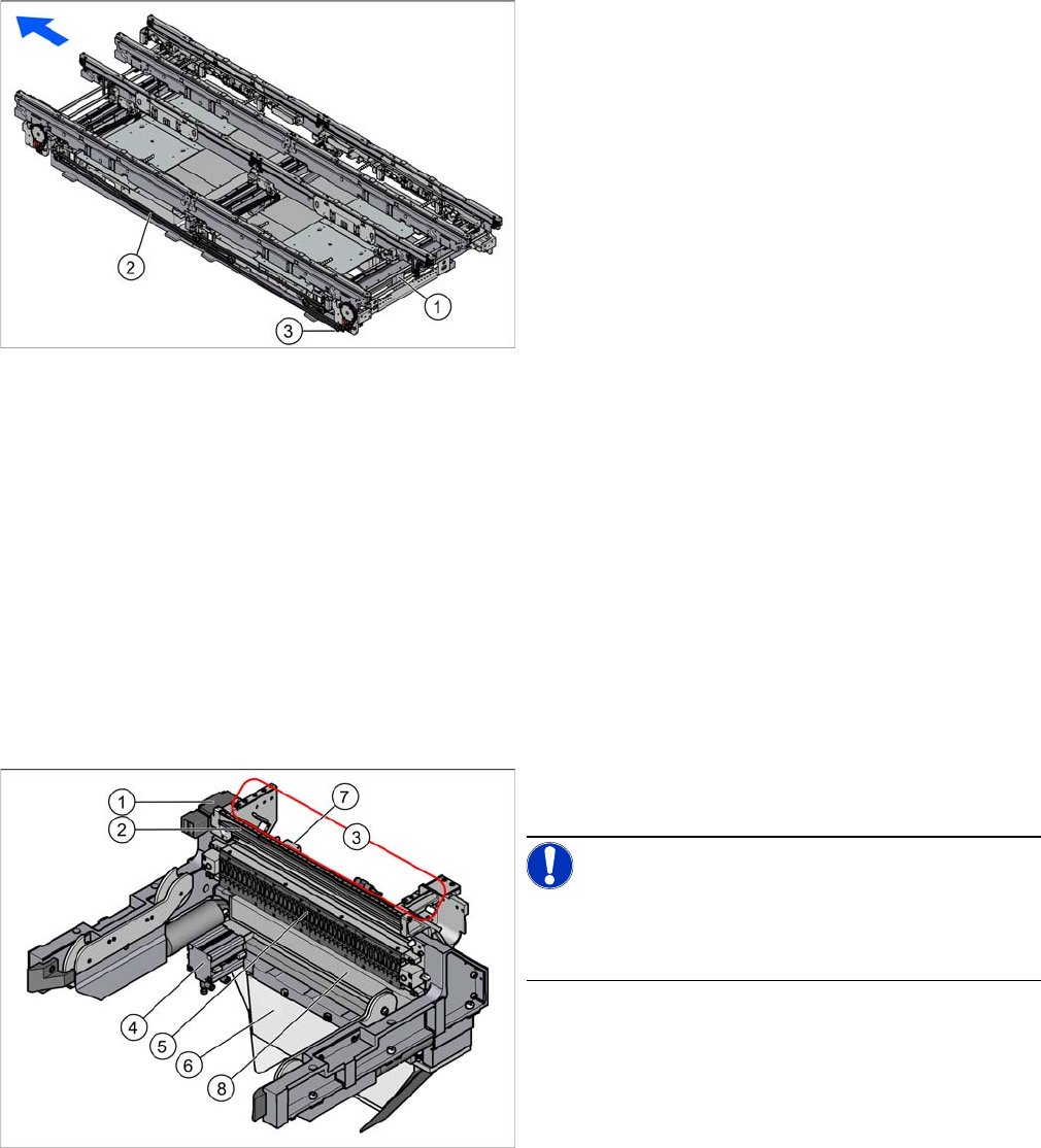
2.9.4 Width Adjustment
Width Adjustment
Function Description
The width is adjusted by means of a motor as programmed. For dual conveyor systems, differing widths
can be set for the two conveyor lanes. The width adjustment uses a motor with its own measuring sys-
tem, meaning that the PCB width can be set independently of other machine components (e.g. the Y
gantry).
The PCB width is adjusted using the width adjustment units. These are moved synchronously back and
forth by the drive motor, with the help of recirculating spindles and a toothed belt.
The side clamp is released by moving out fixing pins. At the same time, the side is fixed to the adjustment
units. After reaching the new PCB width, the fixing pins move back in. The conveyor side is then clamped
again.
2.10
2.10 COT Insert for SX4
COT Insert for SX4
1. Adjustment unit
2. Toothed belt of width adjustment
3. Drive unit of width adjustment
The COT insert is fitted in the SX4 as a default. This is op-
tional for the DX4.
NOTICE!
Please note that the FCU and the spring release differ be-
tween the SX4 and DX4. In the DX4, only every second
feeder track is supported.
1. Safety switch for the component trolley
2. Empty tape duct
3. Assembly positions for the nozzle changers
4. Cutter
5. Feeder control unit (FCU)
6. Waste slide
7. Feed control
8. Feeder unlocking device
Overview of the Modules
2.9.4 Width Adjustment X-Series component trolley
Service Manual SIPLACE SX4/DX4 29
2.11
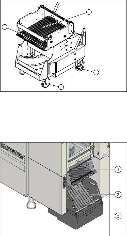
2.11 X-Series component trolley
X-Series component trolley
See also
3.11 X-Series Component Trolley [ ➙ 183]
2.12
2.12 Manual Table for DX4
Manual Table for DX4
See also
3.11 X-Series Component Trolley [ ➙ 183]
1. Guide castor
2. Fixed castor
3. Locking strip
4. Support block
1
4
3
2
1. Upper section
2. Lower section
3. Waste tape container
Overview of the Modules
Cutter 2.9.4 Width Adjustment
30 Service Manual SIPLACE SX4/DX4
2.13
2.13 Cutter
Cutter
2.14
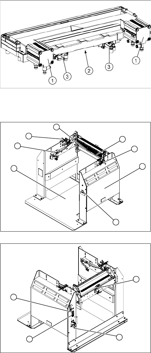
2.14 Docking Station for X-Series Component Trolley
Docking Station for X-Series Component Trolley
1. Pneumatic cylinder
2. Electrical connection
3. Solenoid valves.
1. Docking station – assembly [00116933-xx]
2. Unlocking pushbutton [00334095-xx]
3. Cover (with power pack behind [03025938-XX] and
pressure control valve for locking cylinder)
4. Locking lever [03025104-xx]
5. Feeder unlock device 40-fold [03011582-XX]
6. Feeder Control Unit (FCU)
Prior to FS04: [03020068-xx]
From FS04: [03066685-xx]
7. Short-stroke cylinder for locking unit [03034831-xx]
1. Control valve [03003489-xx]
2. ON/OFF switch
3. Microfuse [03033387-xx]
4. Pressure control valve for bulkcase feeder and main
connection (5.5 bar)
3
4
1
7
6
5
4
2
1
4
3
2