SIPLACE-SX4-DX4-用户手册.pdf - 第170页
Service Work COT inse rt 3.10.1 Replacing the COT Insert Assembly [03080552-xx] 170 Service Manual SIPLACE SX4/DX4 3.10 3 . 1 0 C O T in s e r t COT insert 3.10.1 3 . 1 0 . 1 R e p la c in g t h e C O T I n s e r t A s s…

Service Work
3.9.8 Replacing the Used Tape Chute [03067460-xx] Cutter
Service Manual SIPLACE SX4/DX4 169
Removal
► Loosen the screw fastening the used tape chute
► Take the used tape chute down and out of the machine.
Installation
► Follow the removal instructions in reverse order for installation.
See also
3.13.2 Removing the Back Section of the Manual Table [ ➙ 201]
3.13.3 Removing the Front Section of the Manual Table [ ➙ 202]
3.13.6 Replacing the Feeder Control Unit (FCU) [ ➙ 206]
3.10.3 Replacing the 40-Fold Feeder Unlock Device [03011582-xx] [ ➙ 173]
CAUTION
Risk of cutting
The cutter is located under the tape channel. The blades there have very sharp edges.
► Do not reach into the cutter and make sure that it is never freely accessible for longer peri-
ods.
Service Work
COT insert 3.10.1 Replacing the COT Insert Assembly [03080552-xx]
170 Service Manual SIPLACE SX4/DX4
3.10
3.10 COT insert
COT insert
3.10.1
3.10.1 Replacing the COT Insert Assembly [03080552-xx]
Replacing the COT Insert Assembly [03080552-xx]
Parts, equipment and tools
▪ COT insert SX4 assembly [03080552-xx]
▪ SIPLACE SX4/DX4 detailed circuit diagrams [00196711-xx] (German/English)
▪ Fit-up aid [03015976-xx]
▪ Suitable lifting device (e.g. hand-operated crane)
Removal
► The connection cables and hoses are located behind the COT insert – in the space leading to the
machine base (under the nozzle changer).
► Dismantle the nozzle changer.
► Mark the allocation of all press-fit connections so that you can restore the connections later, with the
new cables. If required, use the detailed circuit diagrams to help you.
► Unplug all connectors and hoses connected to the COT insert.
► Dismantle the side cover on the inside of the location so that you can remove the COT insert later on.
CAUTION
Heavy machine part!
The COT insert is heavy. To lift it out, you will need to use the fit-up aid and a suitable lifting
device (hand-operated crane etc.).
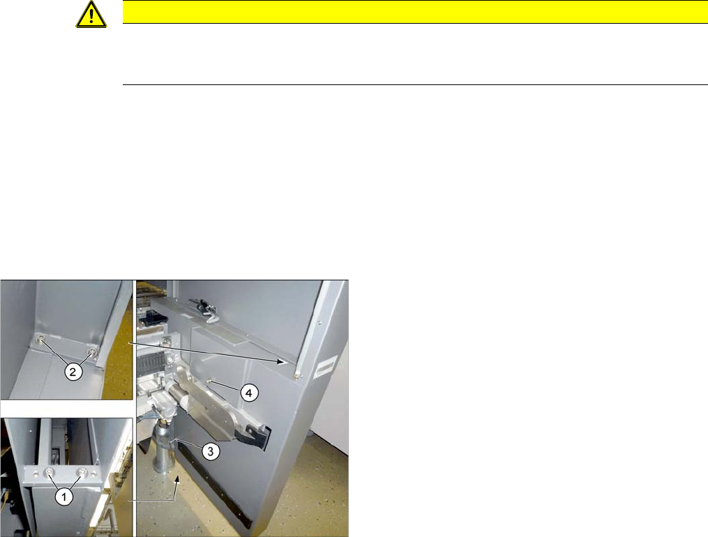
► To do this, loosen the 6 screws fastening the side
cover in the order (1) to (4) and remove these. While
unscrewing, always hold on to the side cover, to pre-
vent it falling off.
Service Work
3.10.1 Replacing the COT Insert Assembly [03080552-xx] COT insert
Service Manual SIPLACE SX4/DX4 171
Installation
► Attach the fit-up aid to the new COT insert and lift it into the machine, with the help of the lifting de-
vice.
► Reconnect all cables. If required, use the detailed circuit diagrams to help you.
► Move the COT insert into its final position (to the previously marked installation position).
Take care not to damage the cables and hoses.
► Loosely screw in the fitting screw and the fastening screws.
► Tighten the fitting screw first.
► Tighten the fastening screws.
► Fit the nozzle changer.
► Refit the side cover.
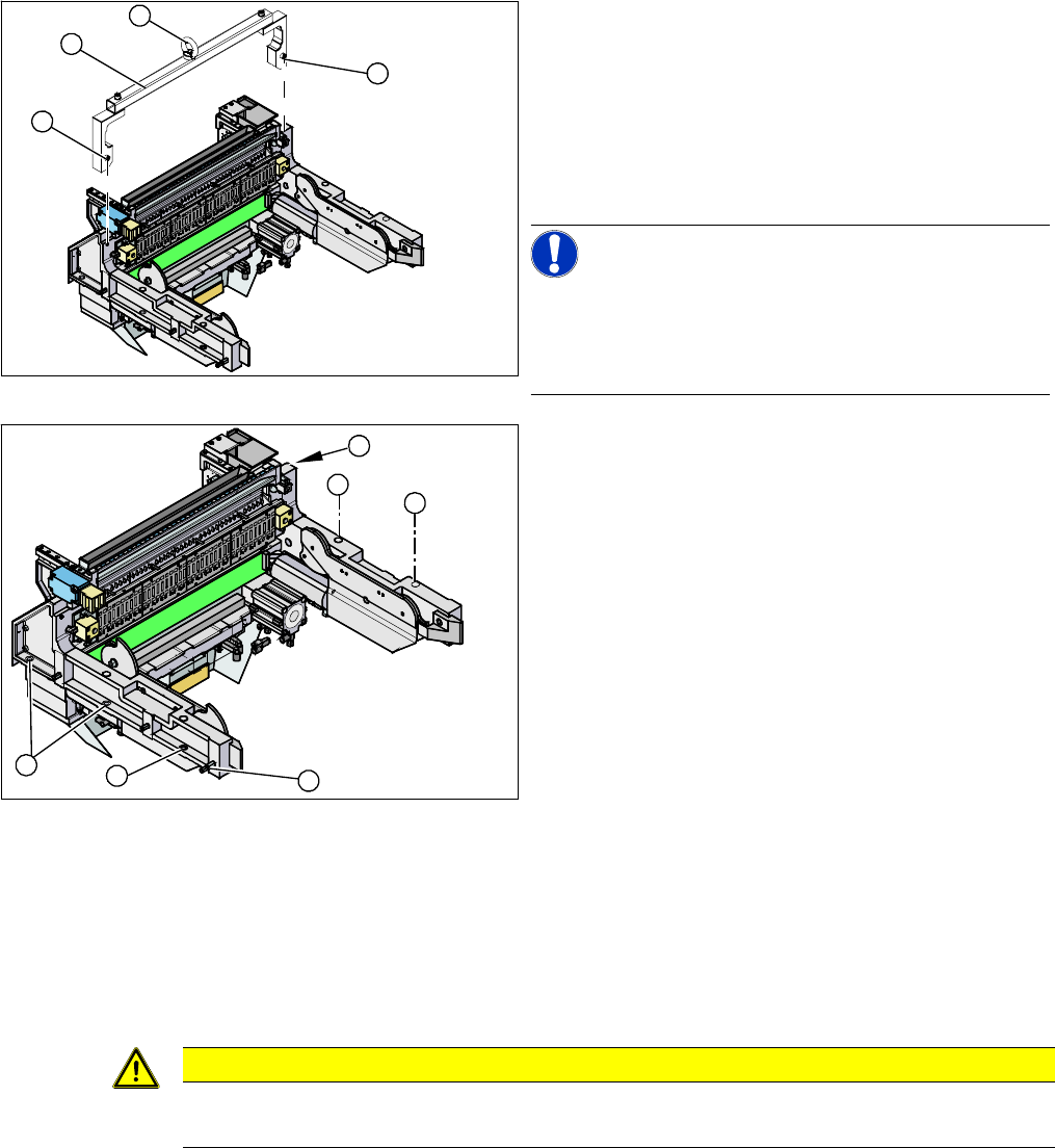
1. Fixtures
2. Fit-up aid
3. Eyelet
► Attach the fit-up aid (2) to the fixtures provided (1) on
the COT insert.
► Fix the lifting device to the eyelet (3) of the fit-up aid
(2).
NOTICE!
The COT insert can be installed at different positions in
the machine location. Mark the position of your COT in-
sert, to ensure that this is subsequently returned to its
original position.
► Loosen the screws fastening the COT insert (1).
► Loosen the fitting screw (2) on the inside of the ma-
chine.
► Lift the complete component trolley feed device out of
the machine and place it on a suitable surface (4
wooden blocks etc.).
► Make sure that you do not damage any valves, con-
nection cables, hoses etc.
1
1
3
2
1
1
1
1
2
1
CAUTION
Observe the specified order!
The fitting screw must be tightened first, before you tighten the other fastening screws.