SIPLACE-SX4-DX4-用户手册.pdf - 第77页
Service Work 3.5.4 Replacing the PCB Camera [03075363-xx] Gantries Service Manual SIPLACE SX4/DX4 77 3.5.4 3 . 5 . 4 R e p la c in g t h e P C B C a m e r a [ 0 3 0 7 5 3 6 3 - x x ] Replacing the PCB Camera [03075363-xx…
Service Work
Gantries 3.5.3 Replacing the Head Plate Sensors (Temperature Sensor) [03071974-xx]
76 Service Manual SIPLACE SX4/DX4
3.5.3
3.5.3 Replacing the Head Plate Sensors (Temperature Sensor) [03071974-xx]
Replacing the Head Plate Sensors (Temperature Sensor) [03071974-xx]
Parts, equipment and tools
▪ Gantry sensor module HCU [03071974-xx]
▪ Heat-conductive paste, if needed
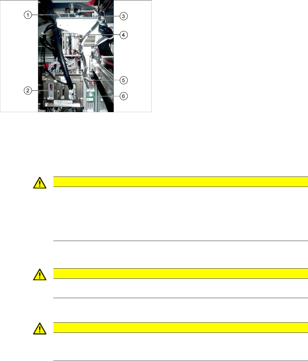
Overview
Removal
► Switch off the machine, disconnect it from the power supply and secure it to prevent unauthorized
reactivation. Observe the instructions in section "1.2 Preparatory Work..." [ ➙ 12].
► Unplug the cable from the head interface, unthread it and loosen all cable ties.
► Undo and remove the two screws fastening the board.
Installation
► Fasten the board with the two screws provided.
SXDX4
► Insert the cable, thread through to the head interface and then connect. Replace the cable ties which
you removed.
1. Vision board
2. Placement head on gantry
3. Head interface
4. Cable from temperature sensor and incremental en-
coder X axis to head interface
5. X axis incremental encoder
6. Temperature sensor
CAUTION
Rubber foam
Under this board there is heat-conductive rubber foam or heat-conductive paste (depends on
version).
► Do not remove the heat-conductive rubber foam.
► The heat-conductive paste needs to be replaced during refitting. You may need to remove
the old heat-conductive paste, if it is still present.
CAUTION
Board underneath
Make sure not to damage the contacts to the board located below.
CAUTION
Check how the cables are run!
Make sure that the end stops (red buffers) do not rub against the cable of the board.
Make sure that the cable for the board can not collide with the X axis end stopper.
Service Work
3.5.4 Replacing the PCB Camera [03075363-xx] Gantries
Service Manual SIPLACE SX4/DX4 77
3.5.4
3.5.4 Replacing the PCB Camera [03075363-xx]
Replacing the PCB Camera [03075363-xx]
Parts, Equipment and Tools
▪ PCB camera (type 34) 28 digital RK [03075363-xx]
Removal
Installation
► Install the new PCB camera on the mount. Tighten the screws and secure with loctite 241.
► Tighten the two screws fastening the damping bracket.
► Run the connection cable to the Vision board and reconnect to the electrical system.
► After replacing the PCB camera, you will need to recalibrate the whole machine. Use the relevant
software function in the Service menu.
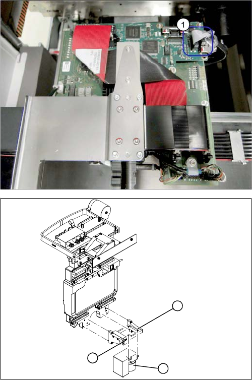
► Unplug the two connection cables X2 and X6 (1) from
the Vision board and unthread as far as the PCB
camera.
► Loosen the two screws on the damping bracket (2).
► Loosen the three screws fastening the PCB camera
(1) mount (3).
1
3
2
Service Work
Gantries 3.5.5 Replacing the Trailing Cable
78 Service Manual SIPLACE SX4/DX4
3.5.5
3.5.5 Replacing the Trailing Cable
Replacing the Trailing Cable
▪ Trailing cable SIPLACE SX4/DX4 2P G [03078380-xx] for gantry 2 and 4
or
Trailing cable SIPLACE SX4/DX4 2P U [03078376-xx] for gantry 1 and 3
3.5.5.1
3.5.5.1 Introduction
Introduction
This manual sometimes uses diagrams of the SIPLACE HF machine. However, this does not affect the
removal or installation work for the SX4/DX4. If there are any differences which need to be taken into
account, these will be indicated separately.
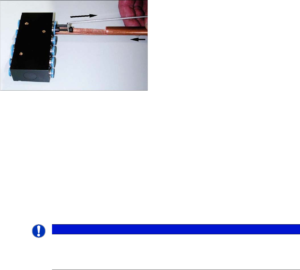
Handling the Hose Unlocking Tool [03047090-xx]
► Use the pipe-shaped tool (1) to open the unlocking ring.
► Carefully pull the hose out of the compressed air connection. The diagram shows the removal of a
dummy plug (2), not a hose.
3.5.5.2
3.5.5.2 Replacing the Trailing Cable for SX4 Machines
Replacing the Trailing Cable for SX4 Machines
Parts, Equipment and Tools
▪ Hose pliers for cutting the pneumatic hose
▪ Hose unlocking tool [03047090-xx]
▪ Pipe/hose cutters [00381443-01]
▪ Retrofitting guide "Vacuum pump on SX4/DX4" [00196845-xx] - if required
▪ Sealing varnish Loctite 241 [02101037-xx]
You will need to order the following parts separately:
▪ Gauge for trailing cable (for gantry 1 and 3 - X4i/SX4/DX4) [00383029-xx]
▪ Gauge for trailing cable (for gantry 2 and 4 - X4i/SX4/DX4) [03063762-xx]
▪ Edding marker, white [00382740-xx]
▪ Press-fit connection QS-6 [03049770-xx] (these are included in the trailing cable package with S
number)
Due to the poor access to the pneumatic distributor, we
recommend using an unlocking tool.
With the help of the hose unlocking tool [03047090-xx]
you can open the unlocking ring (blue here) for the com-
pressed air connection. This enables you to remove both
the hoses and the dummy plugs (additional tool "Unlock-
ing tool for QSC-10H" [03051853-xx]).
NOTICE
No gauge
If there is no gauge available, you can proceed as follows:
► Place the old and new trailing cables next to one another and adjust the length of the new
trailing cable hose. Match the hose lengths to the old trailing cable.