SIPLACE-SX4-DX4-用户手册.pdf - 第80页
Service Work Gantries 3.5.5 Replacing the Trailing Cable 80 Service Manual SIPLACE SX4/DX4 ► Mark the pneumatic hoses through the holes (4) in the ga uge. Observe the position la beled X hose . ► Use the hose pliers to c…
Service Work
3.5.5 Replacing the Trailing Cable Gantries
Service Manual SIPLACE SX4/DX4 79
Preparation
In accordance with your machine's configuration, you will need to remove the relevant modules, covers
and cover plates before you can dismantle the trailing cable.
► Where necessary, remove the cover plates from the gantry trailing cable. Mark their exact position
to ensure correct replacement later.
► Remove the top central cover from the SIPLACE machine.
► Remove the upright covers over the trailing interface gantry, so that you can reach the trailing cable.
Preparing the Trailing Cable
Handling and overview of gauge
The trailing cable is supplied as a complete assembly.
The pneumatic hoses need to be shortened to the exact length of the distance to the pneumatic distrib-
utor on the head mount and in the machine. Use the gauge to help you with this. The existing pneumatic
hoses, which are run in the machine, need to be cut through and connected to the trailing cable at the
exact position, with the help of hose couplings [03049770-01] provided.
There are two gauges available, for the different gantries.
▪ Gauge for trailing cable (for gantry 1 and 3 - X4i/SX4/DX4) [00383029-01]
▪ For the rotated gantry 2 and 4 only - X4i/SX4/DX4:
gauge for trailing cable (for gantry 2 and 4 - X4I) [03063762-01]
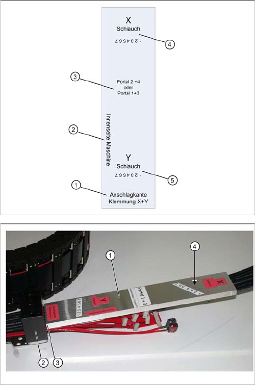
► Observe the designation for the respective gantry on the gauge (1) (gantry 1+3 or gantry 2+4). Se-
lect the correct gauge.
► Place the stopper edge (3) of the gauge (see mark labeled edge for clamp X+ Y on the gauge) at the
edge of the clamping plate (2) for the X trailing cable.
The gauges are labeled to ensure correct handling.
1. Stopper edge for clamp X and Y: this side of the
gauge must be attached to the respective trailing ca-
ble clamp.
2. Machine inside: this side of the gauge must point to
the inside of the machine.
3. Gauge designations
4. X hose: this is where you see the 7 drillings for the X
hose markings.
5. Y hose: this is where you see the 7 drillings for the Y
hose markings.
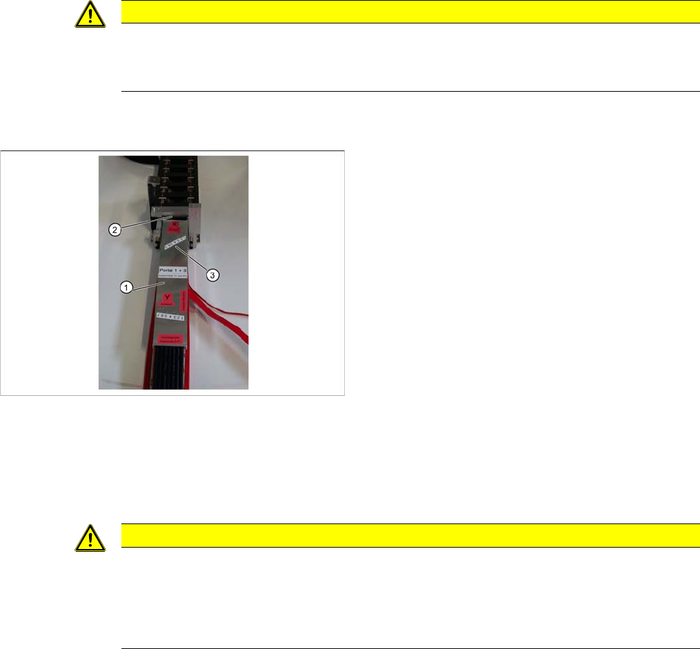
Shortening X hoses at the X trailing cable clamp (to the
pneumatic distributor at the head mount)
1. Gauge for shortening the hoses
2. X trailing cable clamp
3. Stopper edge (gauge at clamp)
4. Hose marking
Service Work
Gantries 3.5.5 Replacing the Trailing Cable
80 Service Manual SIPLACE SX4/DX4
► Mark the pneumatic hoses through the holes (4) in the gauge. Observe the position labeled X hose.
► Use the hose pliers to cut the pneumatic hoses at the marked position. The pneumatic hoses can
now be run inside the pneumatic distributor, with the correct curvature.
► Observe the designation for the respective gantry on the gauge (1) (gantry 1+3 or gantry 2+4). Se-
lect the correct gauge.
► Place the stopper edge (2) of the gauge (see mark labeled edge for clamp X +Y on the gauge) at the
edge of the clamp for the Y axis.
► Mark the pneumatic hoses through the holes (3) in the gauge.
► Use the hose pliers to cut the pneumatic hoses at the marked position. The pneumatic hoses should
now have the correct length and can be connected to the severed pneumatic hoses in the machine
base.
CAUTION
Mark the correct position!
► Observe the position labeled X hose.
► Observe the position marked machine inside on the gauge.
Shortening the Y hoses to the pneumatic distributor in the
machine base
1. Gauge for shortening the hoses
2. Stopper edge at the machine base clamp
3. Hose marking
CAUTION
Mark the correct position!
► Observe the position labeled Y hose.
► To ensure that they have the correct length, cut the pneumatic hoses at the marking labeled
"Y hose". If the pneumatic hoses are cut too short, you will have to discard the entire trailing
cable.
Service Work
3.5.5 Replacing the Trailing Cable Gantries
Service Manual SIPLACE SX4/DX4 81
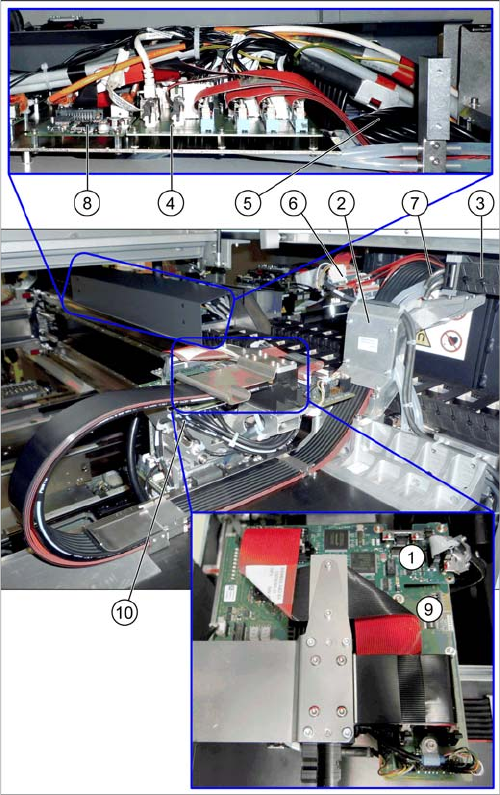
Overview
See also
3.5.5.2.3 Preparing the Trailing Cable [ ➙ 79]
3.5.5.1.1 Handling the Hose Unlocking Tool [03047090-xx] [ ➙ 78]
1. Vision board spread spectrum (VBSX) assembly
[03067289-xx]
This board is located at the top of the head interface.
2. Trailing cable console
3. Power track chain
4. Trailing interface for gantry
Gantry 2 and 4 [03071356-xx]
Gantry 1 and 3 [03071355-xx]
5. Pneumatic hoses to the pneumatic distributor (in the
machine base)
6. Gantry interface
Gantry 2 and 4 [03059909-xx]
Gantry 1 and 3 [03059908-xx]
7. Connection piece for cooling tubes to Y motor
8. Vision hotlink adapter VHA [03050555-xx]
9. MODULE/Head interface
C700X-L [03055068-xx]
C700X-R [03055070-xx]
10. Pneumatic distributor