SIPLACE-SX4-DX4-用户手册.pdf - 第67页
Service Work 3.4.5 Replacing the Proportional Con troller (Location 4) [03065 425-xx] Pneumatic System Service Manual SIPLACE SX4/DX4 67 Removal ► Switch off the machine, disconnec t it from the po wer supply and secure …
Service Work
Pneumatic System 3.4.5 Replacing the Proportional Controller (Location 4) [03065425-xx]
66 Service Manual SIPLACE SX4/DX4
Installation
► Follow the removal instructions in reverse order for installation. Also observe the following instruc-
tions:
3.4.5
3.4.5 Replacing the Proportional Controller (Location 4) [03065425-xx]
Replacing the Proportional Controller (Location 4) [03065425-xx]
Parts, equipment and tools
▪ Proportional controller Sentronic-D DN8 SUBB1/4 10 bar [03065425-xx]
▪ Adapter plate proportional valve [03082780-xx] (seal)
▪ ISO4762-M4x70-A2-70 [03082432-xx]
Overview
CAUTION
Installation instructions
► Seal the compressed air system with sealant. Observe the instructions in section "3.4.2
Sealing the Screwed Connections" [ ➙ 64] in connection with this.
NOTICE
Parameter
The proportional controller is supplied with the latest parameters preset. Subsequent program-
ming is not possible.
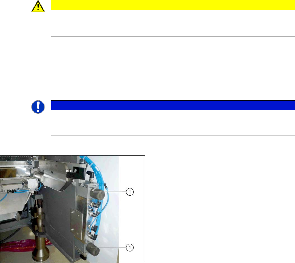
1. Proportional controller top and bottom
Service Work
3.4.5 Replacing the Proportional Controller (Location 4) [03065425-xx] Pneumatic System
Service Manual SIPLACE SX4/DX4 67
Removal
► Switch off the machine, disconnect it from the power supply and secure it to prevent unauthorized
reactivation. Observe the instructions in section "1.2 Preparatory Work..." [ ➙ 12].
► To do this, loosen the screws fastening the side cover and remove these. (See "3.4.3 Dismantling
the Lower Side Cover" [ ➙ 64])
► Unplug all electrical and pneumatic connections to the proportional controller. You may want to mark
their positions, to make clear assignment easier later on.
► Loosen the screws fastening the proportional controller and then remove the controller.
Installation
► Follow the removal instructions in reverse order for installation. Also observe the following instruc-
tions:
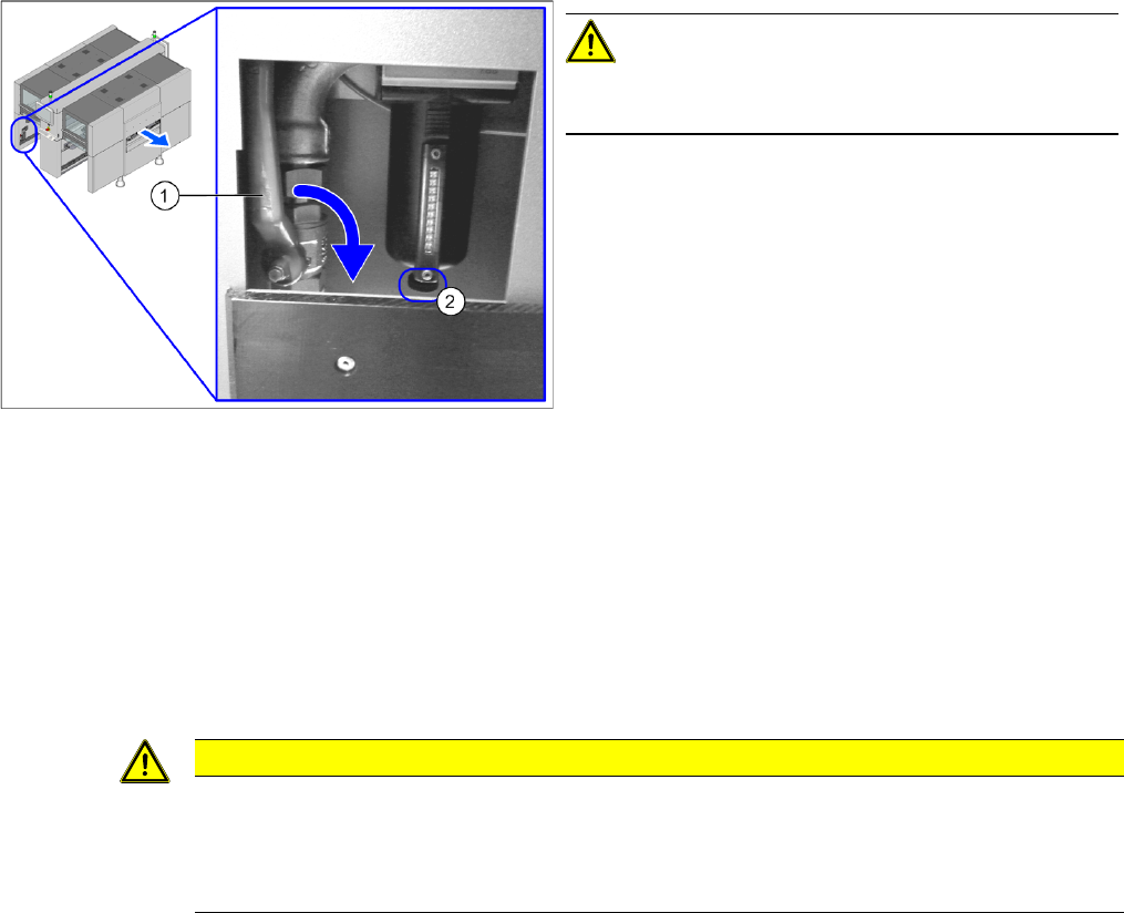
CAUTION!
When working on the pneumatic system, always switch
off the compressed air supply.
► Push the lever (1) for the compressed air supply
back, until it is positioned horizontally.
► Open the screw (2) on the inlet filter to vent the sys-
tem.
► All manometers must be set to zero.
CAUTION
Installation instructions
► Clean the sealing rings and the adapter plate and insert these again.
► Seal the compressed air system with sealant. Observe the instructions in section "3.4.2
Sealing the Screwed Connections" [ ➙ 64] in connection with this.
Service Work
Pneumatic System 3.4.6 Buffer Module for Autorecovery Option [03086425-xx]
68 Service Manual SIPLACE SX4/DX4
3.4.6
3.4.6 Buffer Module for Autorecovery Option [03086425-xx]
Buffer Module for Autorecovery Option [03086425-xx]
Parts, equipment and tools
▪ Buffer module DC24V UF20.241 for autorecovery [03086425-xx]
Removal/installation
3.4.7
3.4.7 Replacing the Side Channel Compressor Elmo Blower (Location 3) [03004094-xx]
Replacing the Side Channel Compressor Elmo Blower (Location 3) [03004094-xx]
Parts, equipment and tools
▪ Side channel compressor ELMO blower [03004094-xx]
Overview
NOTICE
See the assembly instructions
For removal and installation information, refer to the "Autorecovery X/SX" assembly instruc-
tions[00196853-xx] (German/English).
CAUTION
Installation instructions
► Seal the compressed air system with sealant. Observe the instructions in section "3.4.2
Sealing the Screwed Connections" [ ➙ 64] in connection with this.
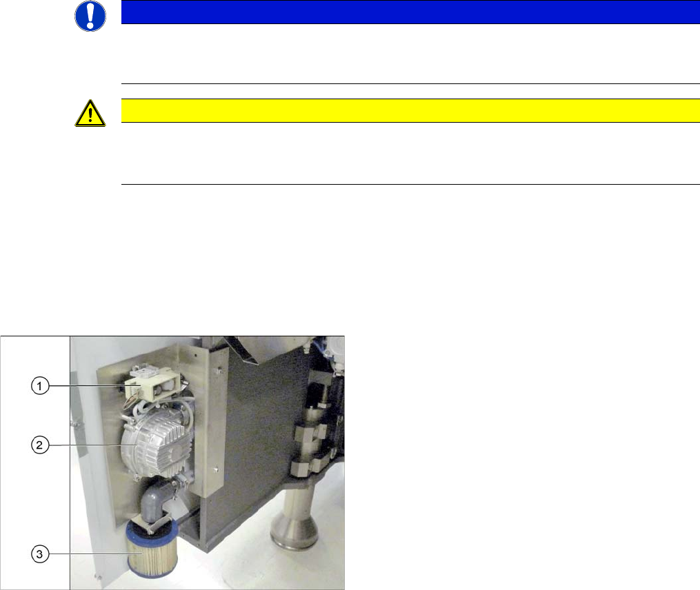
1. Elmo blower electrics
2. Elmo blower
3. Cooling air filter
The ELMO blower is located at location 3, behind the side
cover.