SIPLACE-SX4-DX4-用户手册.pdf - 第22页
Overview of the Modules Twin Head 2.2.1 Differentiation of the C&P20 heads 22 Service Manual SIPLACE SX4/DX4 2.4 2 . 4 T w in H e a d Twin Head 2.5 2 . 5 C P P H e a d CPP Head The TwinHead consists of 2 Pick&Pla…
Overview of the Modules
2.2.1 Differentiation of the C&P20 heads C&P20 Nozzle Changer
Service Manual SIPLACE SX4/DX4 21
2.3
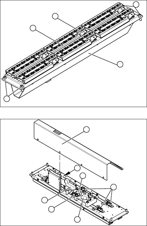
2.3 C&P20 Nozzle Changer
C&P20 Nozzle Changer
1. Cover (covering complete electronic and pneumatic
systems)
2. Toggle (six of them)
3. Nozzle magazine
4. Fastening screws
1. Cover (2 x 4 fastening screws)
2. Control board NC
3. Valve assembly
4. Swivel drive
5. Microswitch (six of them)
6. Green LED 3 mm
4
1
4
3
2
5
1
6
5
4
3
2
Overview of the Modules
Twin Head 2.2.1 Differentiation of the C&P20 heads
22 Service Manual SIPLACE SX4/DX4
2.4
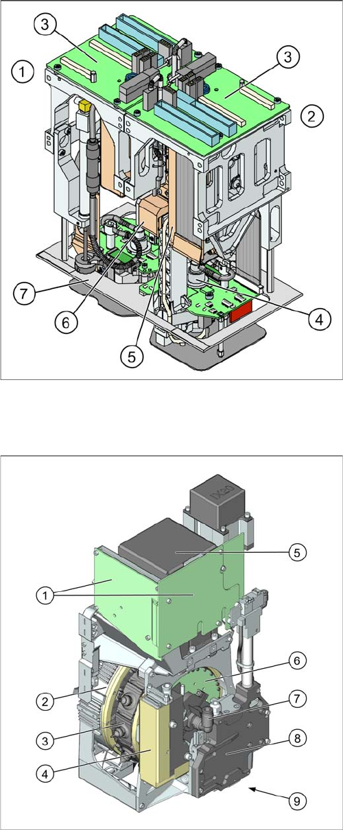
2.4 Twin Head
Twin Head
2.5
2.5 CPP Head
CPP Head
The TwinHead consists of 2 Pick&Place modules.
1. Module 1
2. Module 2, rotated by 180° compared to module 1.
3. Main board on relevant module
4. D axis
5. Linear motor Z axis
6. Z axis incremental measurement system
7. Camera lens hood TwinHead
X-Series S, SX4/DX4, X-Series, HF: [03001846-xx]
SX1/SX2/DX1/DX2 [03079524-xx]
CPP placement head with camera SST29
[03070108-xx]
CPP placement head without camera
[03053528-xx]
1. Intermediate distributor 1 and 2 (ID1, ID2)
2. Star motor (integrated in head housing)
3. DP axis (as direct drive)
4. Pressure control valve
5. Component camera (behind the intermediate distrib-
utor, standard: SST29)
6. Single core solution (SCS) – DP drive control
7. Holding circuit supply, integrated venturi nozzles and
valve assembly (valve terminal)
8. Z axis with return cylinder
9. Component sensor in the pick and place position (on
the underside)
Overview of the Modules
2.6.1 BoxPC 627B (DX4) Electrical System
Service Manual SIPLACE SX4/DX4 23
2.6
2.6 Electrical System
Electrical System
2.6.1
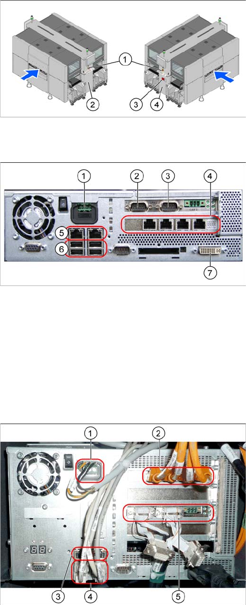
2.6.1 BoxPC 627B (DX4)
BoxPC 627B (DX4)
See also
3.3.2 Replacing the CAN Card [03079973-xx] [ ➙ 59]
3.3.3 Replacing the Hotlink Interface Card [03052135-xx] [ ➙ 60]
1.2 Preparatory Work... [ ➙ 12]
3.3.4 Replacing the BoxPC Memory Extension [03086337-xx] [ ➙ 61]
2.6.2
2.6.2 BoxPC 827B (SX4)
BoxPC 827B (SX4)
1. EMERGENCY STOP button
2. HCU, GCU, BoxPC (behind the cover)
3. Main power switch
4. Power supply (behind the cover)
1. Power supply DC 24 V
2. CAN 1
3. CAN 2
4. Hotlink card
5. LAN connections
6. USB connections
7. DVI/VGA monitor connection
1. Power supply
2. Hotlink interface
3. LAN connections
4. USB connections
5. CAN card