SIPLACE-SX4-DX4-用户手册.pdf - 第161页
Service Work 3.9.5 Replacing the Solenoid Valves [03 000630-xx] Cutter Service Manual SIPLACE SX4/DX4 161 ► Connect the compressed air hoses to the cylinder in the correct allocation. ► Further installation is performe d…
Service Work
Cutter 3.9.4 Replacing the Short-Stroke Cylinder [03038587-xx]
160 Service Manual SIPLACE SX4/DX4
3.9.4
3.9.4 Replacing the Short-Stroke Cylinder [03038587-xx]
Replacing the Short-Stroke Cylinder [03038587-xx]
Parts, equipment and tools
▪ Short-stroke cylinder 50x40 ECDQ2B50-0040-CEJ00119 [03038587-xx]
▪ Loctite 241 [02101037-xx]
Removal
► Remove the cutter from the machine (see "3.9.1 Replacing the Cutter on the COT Insert [03066690-
xx]" [ ➙ 154]).
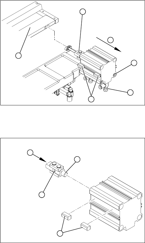
Installation
► Remove the articulated joint (5) (see "3.9.3 Replac-
ing the Articulated Joint on the Short-Stroke Cylinder
[03000518-xx]" [ ➙ 158]).
► Use a permanent marker to mark the exact installa-
tion position of the proximity switch (1) on the short-
stroke cylinder.
► Loosen the screws fastening the two inductive prox-
imity switches (1) to the short-stroke cylinder.
► Remove the compressed air connections (2) on the
short-stroke cylinder. You may want to mark their po-
sitions, to make clear assignment easier later on.
► Remove the two screws (3) holding the short-stroke
cylinder.
► Remove the short-stroke cylinder (4) from the cutter.
1
6
5
4
3
2
► Apply a small amount of Loctite no. 241 to the thread
(2) of the new joint.
► Screw the articulated joint (1) into the short-stroke
cylinder.
► Turn the articulated joint in its installation position (3).
Once the cylinder is installed, the slot in the moveable
blade prevents the articulated joint from turning.
► Copy the exact installation position of the proximity
switch (4) onto the new short-stroke cylinder (e.g.
with a feeler gauge, fine-tipped marker pen).
1
4
3
2
Service Work
3.9.5 Replacing the Solenoid Valves [03000630-xx] Cutter
Service Manual SIPLACE SX4/DX4 161
► Connect the compressed air hoses to the cylinder in the correct allocation.
► Further installation is performed by following the above instructions in the reverse order. Also ob-
serve section "3.9.3 Replacing the Articulated Joint on the Short-Stroke Cylinder [03000518-xx]"
[ ➙ 158].
3.9.5
3.9.5 Replacing the Solenoid Valves [03000630-xx]
Replacing the Solenoid Valves [03000630-xx]
Parts, Equipment and Tools
▪ Solenoid valve [03000630-xx]
Overview
Removal/Installation
► Loosen the compressed air connections on the solenoid valve.
► Unplug the press-fit connection on the solenoid valve connection cable.
► Loosen the screws holding the solenoid valve in place and remove the solenoid valve.
► Mount the new solenoid valve and make the press-fit connection to the valve.
Attach cables ties, if necessary (strain relief).
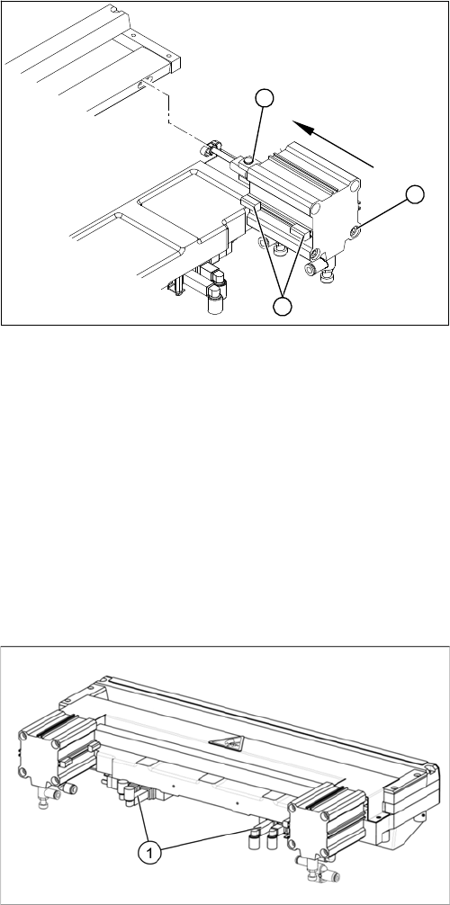
► Install the proximity switch (1) precisely in the position
you marked with the permanent marker.
► Place the prepared cylinder into the cutter, in the cor-
rect rotary position of the articulated joint (2).
► Fasten the cylinder in this position, with the two
screws provided (3) (Loctite 241).
1
3
2
Cutter (using example of X series)
1. Position of the solenoid valves
Service Work
Cutter 3.9.6 Replacing the Proximity Switch [03063590]
162 Service Manual SIPLACE SX4/DX4
3.9.6
3.9.6 Replacing the Proximity Switch [03063590]
Replacing the Proximity Switch [03063590]
Parts, equipment and tools
▪ Proximity switch with cable (incl. four signal transmitters) [03063590-xx]
Overview
Removal/installation
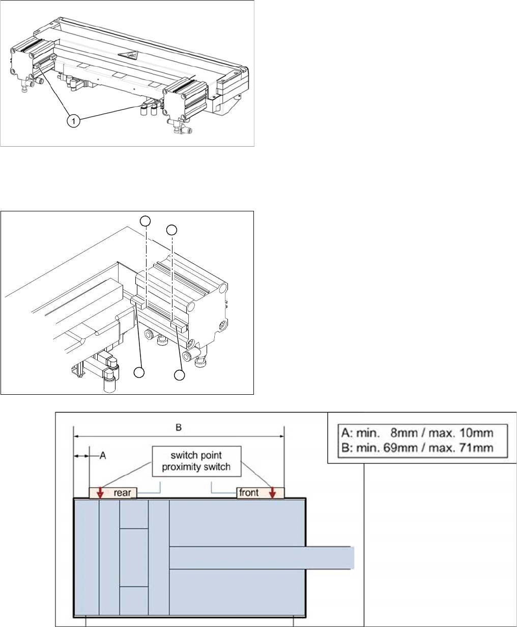
Cutter (using example of X series)
1. Two proximity switches on each short-stroke cylinder
► To make subsequent checking easier, use a perma-
nent marker to mark the exact installation position (3)
of the proximity switch (1) or (2) on the short-stroke
cylinder.
► Loosen the screw fastening the proximity switch to
the short-stroke cylinder.
► Unplug the connection cable.
► Fit the proximity switch at the positions shown in the
following diagram. These should match the positions
marked (3).
► Secure the fastening screws with locking varnish.
► Reconnect to the electricity supply.
► Check the switching points of the proximity switches.
1
2
3
3