SIPLACE-SX4-DX4-用户手册.pdf - 第242页
Settings Gantry Settings 5.4.6 Track Signals and Zero Pulse 242 Service Manual SIPLACE SX4/DX4 X10 on the gantry Interface for the Y Axis X24 on the Head Inter face for the X Axis 5.4.6.2 5 . 4 . 6 . 2 C h e c k in g t h…
Settings
5.4.6 Track Signals and Zero Pulse Gantry Settings
Service Manual SIPLACE SX4/DX4 241
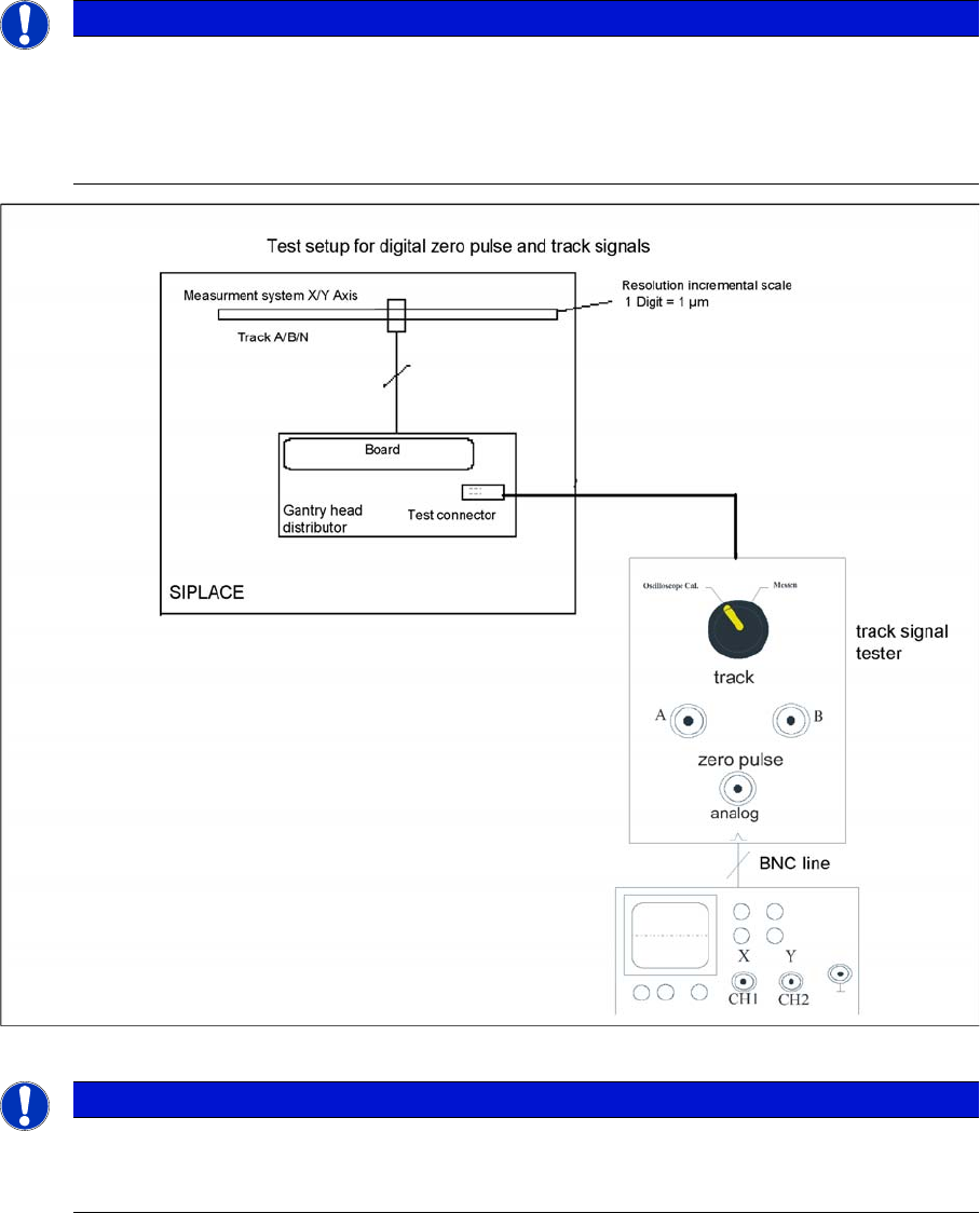
Measuring the Digital Zero Pulse Signal
Measurement procedure for checking the digital zero pulse signal and the digital track signals.
NOTICE
Checking the zero pulse
You can also use the BNC socket on the axis test box to check the zero pulse signal (inverted
display of zero pulse signal). The digital signals (for error monitoring purposes) can be checked
at connectors X10 and X24 of the gantry and head interface. (Calculate extra time for Y axes,
dismounting the covers).
NOTICE
Measurement procedure
The procedure for measuring the digital zero pulse is identical to that for measuring the analog
zero pulse.
Settings
Gantry Settings 5.4.6 Track Signals and Zero Pulse
242 Service Manual SIPLACE SX4/DX4
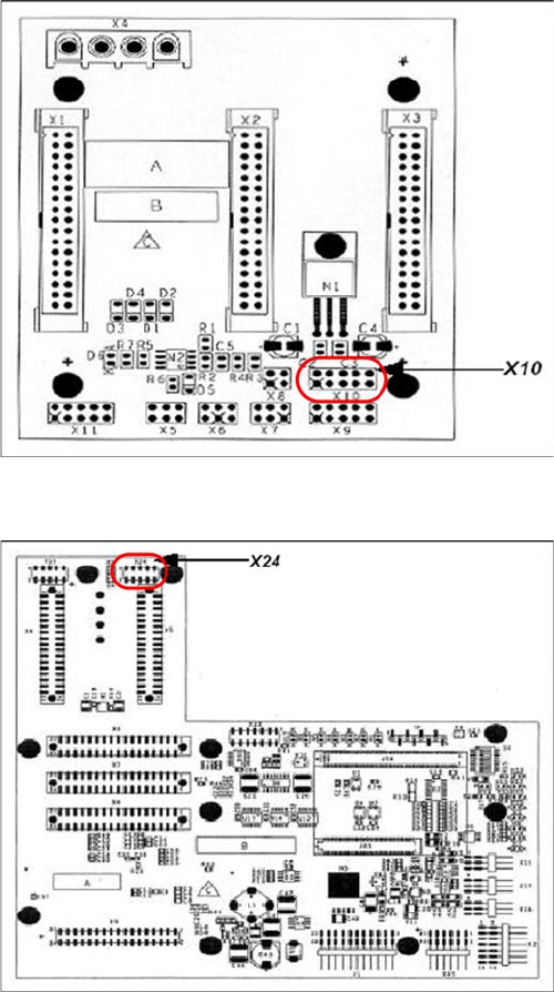
X10 on the gantry Interface for the Y Axis
X24 on the Head Interface for the X Axis
5.4.6.2
5.4.6.2 Checking the Track Signals
Checking the Track Signals
Analog Track Signals
To check the track signals, connect the track signal tester and the oscilloscope. (see "5.4.6.1.1 Measur-
ing the Analog Zero Pulse Signal" [ ➙ 239])
► Switch the machine "ON"
► Switch the track signal tester to Calibrate the oscilloscope
► Set the oscilloscope to DC, Refr., Non Store, Auto (20 ms)
► Voltages V/Division decrease up to 0.5 V/Div.
► Set the oscilloscope to X/Y --> an illuminated point will appear!
► Move the point into the middle of the display.
► Set the measuring system tester to Sinus amplifier output
► Manually move the selected axis back and forth.
Connector assignment X10:
1. Pin 1 Ground
2. Pin 2 Track A
3. Pin 3 Track A\
(A\ means inverted A)
4. Pin 4 Ground
5. Pin 5 Track B
6. Pin 6 Track B\
7. Pin 7 +5V
8. Pin 8 Track N
9. Pin 9 Track N\
10. Pin 10 Key
Connector assignment X24:
1. Pin 1 Ground
2. Pin 2 Track A
3. Pin 3 Track A\
4. Pin 4 Ground
5. Pin 5 Track B
6. Pin 6 Track B\
7. Pin 7 +5V
8. Pin 8 Track N
9. Pin 9 Track N\
10. Pin 10 Key
Settings
5.4.6 Track Signals and Zero Pulse Gantry Settings
Service Manual SIPLACE SX4/DX4 243
Digital Track Signals
To check the digital track signals, connect the track signal tester and the oscilloscope. (see "5.4.6.1.2
Measuring the Digital Zero Pulse Signal" [ ➙ 241])
The measurement sequence is identical to that described in "5.4.6.2.1 Analog Track Signals" [ ➙ 242].
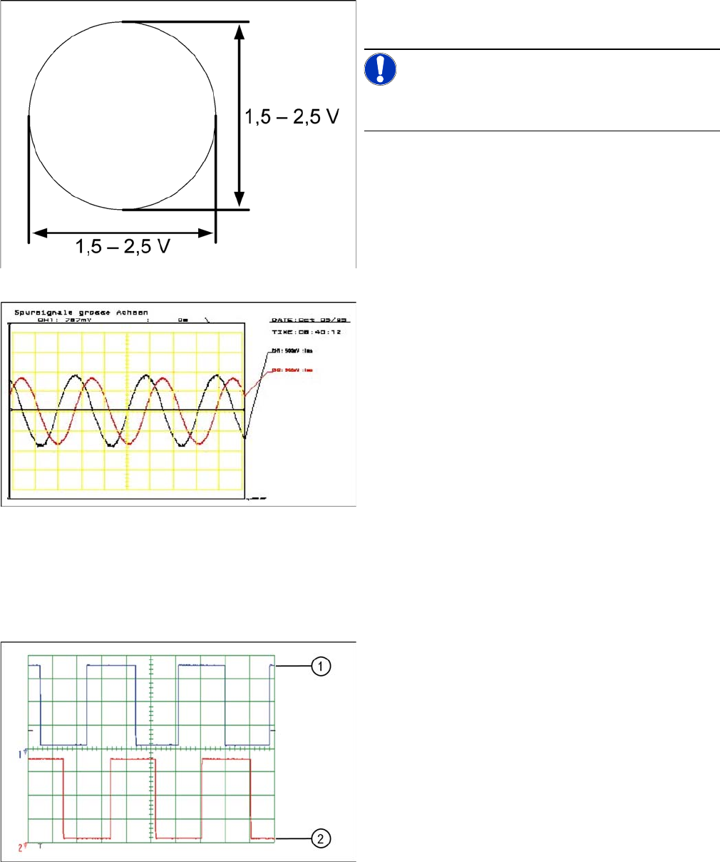
Analog track signals A and B in X/Y oscilloscope mode
► The adjacent picture should appear on the oscillo-
scope.
NOTICE!
A new version of the incremental encoder (one field lens)
can recognize signals from 1.8 to 3.6 Vss.
Analog track signals 90° phase shift
► Switch the oscilloscope to normal operation.
► The adjacent picture should appear on the oscillo-
scope.
Digital track signals 90° phase shift
1. Track A
2. Track B