SIPLACE-SX4-DX4-用户手册.pdf - 第70页
Service Work Pneumatic System 3.4.8 Replacing the Electronic Ballast for the ELMO Blower [0 3006517-xx] 70 Service Manual SIPLACE SX4/DX4 3.4.8 3 . 4 . 8 R e p la c in g t h e E le c t r o n ic B a lla s t f o r t h e E …
Service Work
3.4.7 Replacing the Side Channel Compressor Elmo Blower (Location 3) [03004094-xx] Pneumatic System
Service Manual SIPLACE SX4/DX4 69
Removal
► Switch off the machine, disconnect it from the power supply and secure it to prevent unauthorized
reactivation. Observe the instructions in section "1.2 Preparatory Work..." [ ➙ 12].
► To do this, loosen the screws fastening the side cover and remove these. (See "3.4.3 Dismantling
the Lower Side Cover" [ ➙ 64])
► Unplug all electrical and pneumatic connections to the Elmo blower. You may want to mark their po-
sitions, to make clear assignment easier later on.
► Loosen the screws fastening the Elmo blower and then remove it.
Installation
► Follow the removal instructions in reverse order for installation. Also observe the following instruc-
tions:
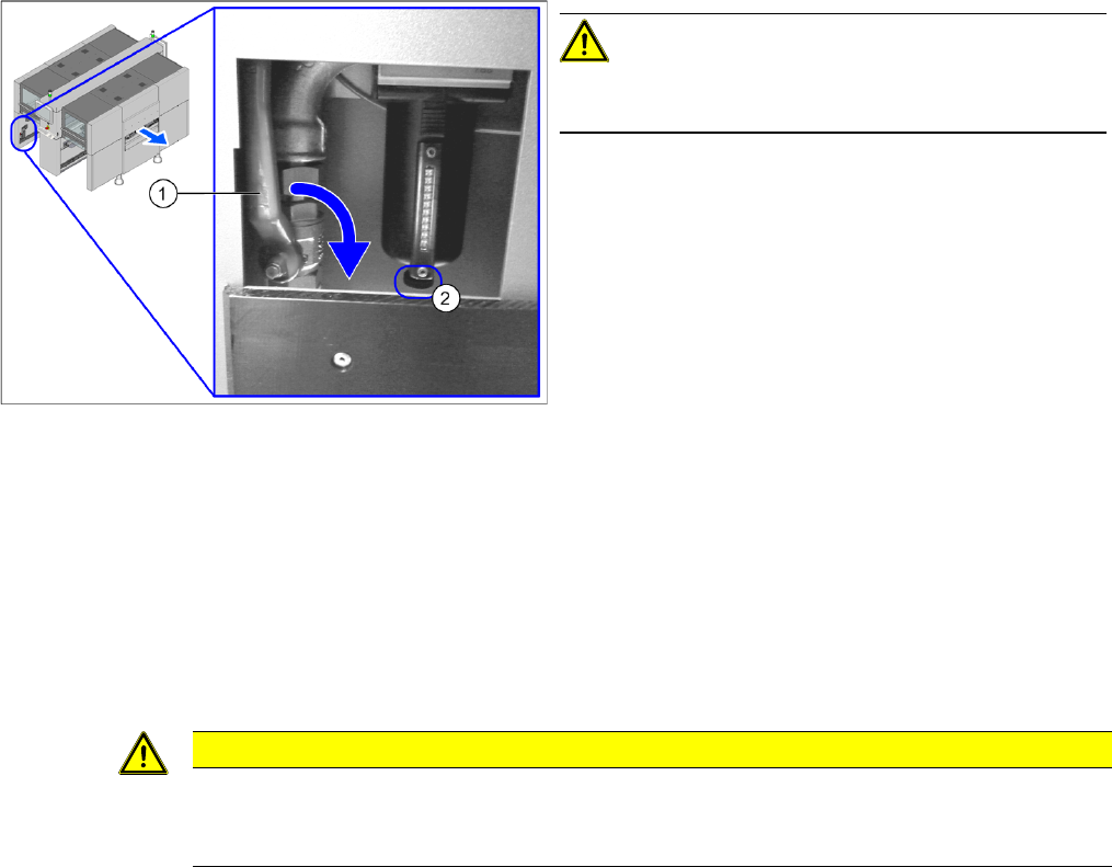
CAUTION!
When working on the pneumatic system, always switch
off the compressed air supply.
► Push the lever (1) for the compressed air supply
back, until it is positioned horizontally.
► Open the screw (2) on the inlet filter to vent the sys-
tem.
► All manometers must be set to zero.
CAUTION
Installation instructions
► Seal the compressed air system with sealant. Observe the instructions in section "3.4.2
Sealing the Screwed Connections" [ ➙ 64] in connection with this.
Service Work
Pneumatic System 3.4.8 Replacing the Electronic Ballast for the ELMO Blower [03006517-xx]
70 Service Manual SIPLACE SX4/DX4
3.4.8
3.4.8 Replacing the Electronic Ballast for the ELMO Blower [03006517-xx]
Replacing the Electronic Ballast for the ELMO Blower [03006517-xx]
Parts, equipment and tools
▪ Electronic ballast for ELMO blower [03006517-xx]
Overview
Removal
► Switch off the machine, disconnect it from the power supply and secure it to prevent unauthorized
reactivation. Observe the instructions in section "1.2 Preparatory Work..." [ ➙ 12].
► To do this, loosen the screws fastening the side cover and remove these. (See "3.4.3 Dismantling
the Lower Side Cover" [ ➙ 64])
► Unplug all electrical and pneumatic connections to the Elmo blower electrics. You may want to mark
their positions, to make clear assignment easier later on.
► Loosen the screws fastening the Elmo blower electrics and then remove these electrics.
Installation
► Follow the removal instructions in reverse order for installation.
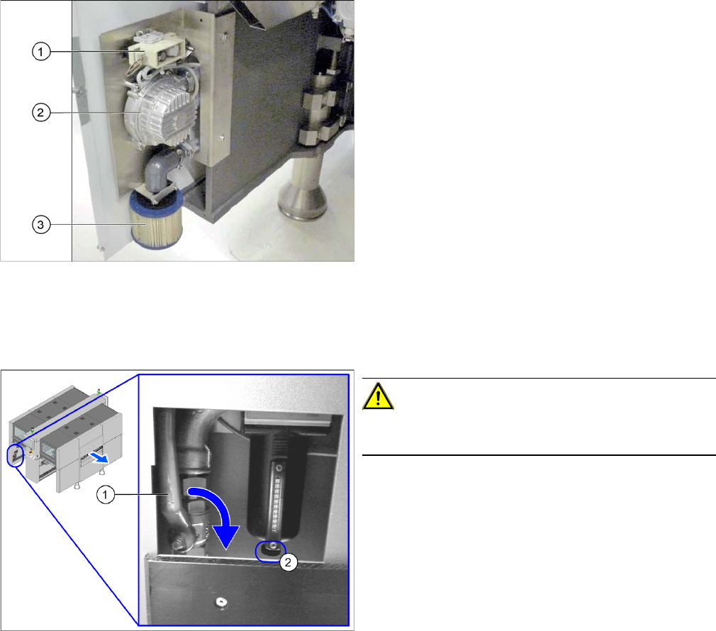
1. Elmo blower electrics
2. Elmo blower
3. Cooling air filter
The ELMO blower is located at location 3, behind the side
cover.
CAUTION!
When working on the pneumatic system, always switch
off the compressed air supply.
► Push the lever (1) for the compressed air supply
back, until it is positioned horizontally.
► Open the screw (2) on the inlet filter to vent the sys-
tem.
► All manometers must be set to zero.
Service Work
3.5.1 Replacing the X Axis Incremental Encoder [03020588-xx] Gantries
Service Manual SIPLACE SX4/DX4 71
3.5
3.5 Gantries
Gantries
3.5.1
3.5.1 Replacing the X Axis Incremental Encoder [03020588-xx]
Replacing the X Axis Incremental Encoder [03020588-xx]
Parts, equipment and tools
▪ Read head MS22.74 X/Y 677mm [03090201-xx] (replaces: [03020588-xx])
Overview
Press-fit connections
NOTICE
Head interface
The new read head for the X axis "Read head MS22.74 X/Y 677mm" [03090201-xx] may only
be fitted with a "head interface" from FS05 [03055067-05].
The read head can only be fitted together with the new "Tape measure X axis SX4" [03092558-
xx]. If an old read head is upgraded to the new version MS22, you will also need to replace the
scale.
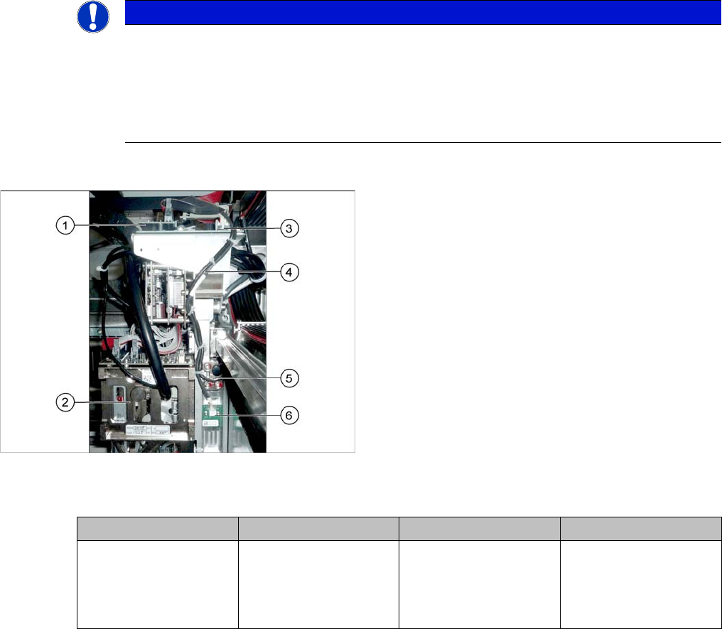
1. Vision board
2. Placement head on gantry
3. Head interface
4. Cable from temperature sensor and incremental en-
coder X axis to head interface
5. X axis incremental encoder
6. Temperature sensor
Assembly Gantry Board Terminals
X axis incremental en-
coder
Gantry 1 Head interface
[03055068-xx]
X15ac (gantry 1)
X15bc (gantry 2)
X15cc (gantry 3)
X15dc (gantry 4)