SIPLACE-SX4-DX4-用户手册.pdf - 第129页
Service Work 3.6.21 Replacing the Ultras onic Sensor PXS240 [03069863- xx] Conv eyor Service Manual SIPLACE SX4/DX4 129 Installation ► Follow the removal inst ructions in reverse orde r fo r in stallati on of the ne w u …
Service Work
Conveyor 3.6.21 Replacing the Ultrasonic Sensor PXS240 [03069863-xx]
128 Service Manual SIPLACE SX4/DX4
Removal
► Use the software to move the conveyor sides into the position which allows you best access. As an
alternative, you can loosen the clamps for the relevant sides in dual conveyors.
► Switch off the machine, disconnect it from the power supply and secure it to prevent unauthorized
reactivation. Observe the instructions in section "1.2 Preparatory Work..." [ ➙ 12].
► Dismantle the cover plate on the sensor rail.
If you need to replace the ultrasonic sensor behind the conversion board, perform the steps described
below:
► Remove a different, functional ultrasonic sensor from the rail by following the instructions above.
(You can then fit the new ultrasonic sensor in its place.)
► Fit this ultrasonic sensor in the position behind the conversion board and reestablish all connections
to the ultrasonic sensor.
► Fit the conversion board and reestablish all connections to it.
Background: the ultrasonic sensor behind the conversion board is not easily accessible for any teaching
procedures which may be required. This exchange of sensors means that this ultrasonic sonar does not
need to be taught.
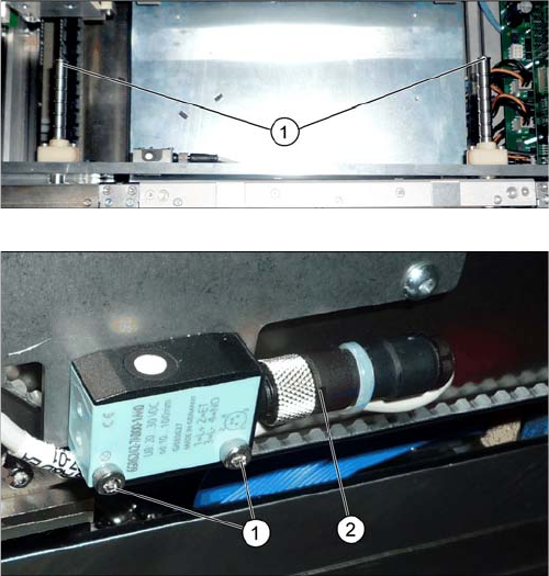
► If needed, the sensor rail can be removed to allow
better access. Simply loosen the two screws (1) on
the ends of both shafts.
► If you need to replace the ultrasonic sensor behind
the conversion board, dismantle it first. Unplug all
connections. You may want to mark the positions, to
make clear assignment easier later on.
► Loosen the screws (1) fastening the ultrasonic sen-
sors.
► Unscrew the press-fit connection (2) from the ultra-
sonic sensor and remove the ultrasonic sensor from
the machine.
Service Work
3.6.21 Replacing the Ultrasonic Sensor PXS240 [03069863-xx] Conveyor
Service Manual SIPLACE SX4/DX4 129
Installation
► Follow the removal instructions in reverse order for installation of the new ultrasonic sensor. Also ob-
serve the following instructions:
Assembly at the stopper positions
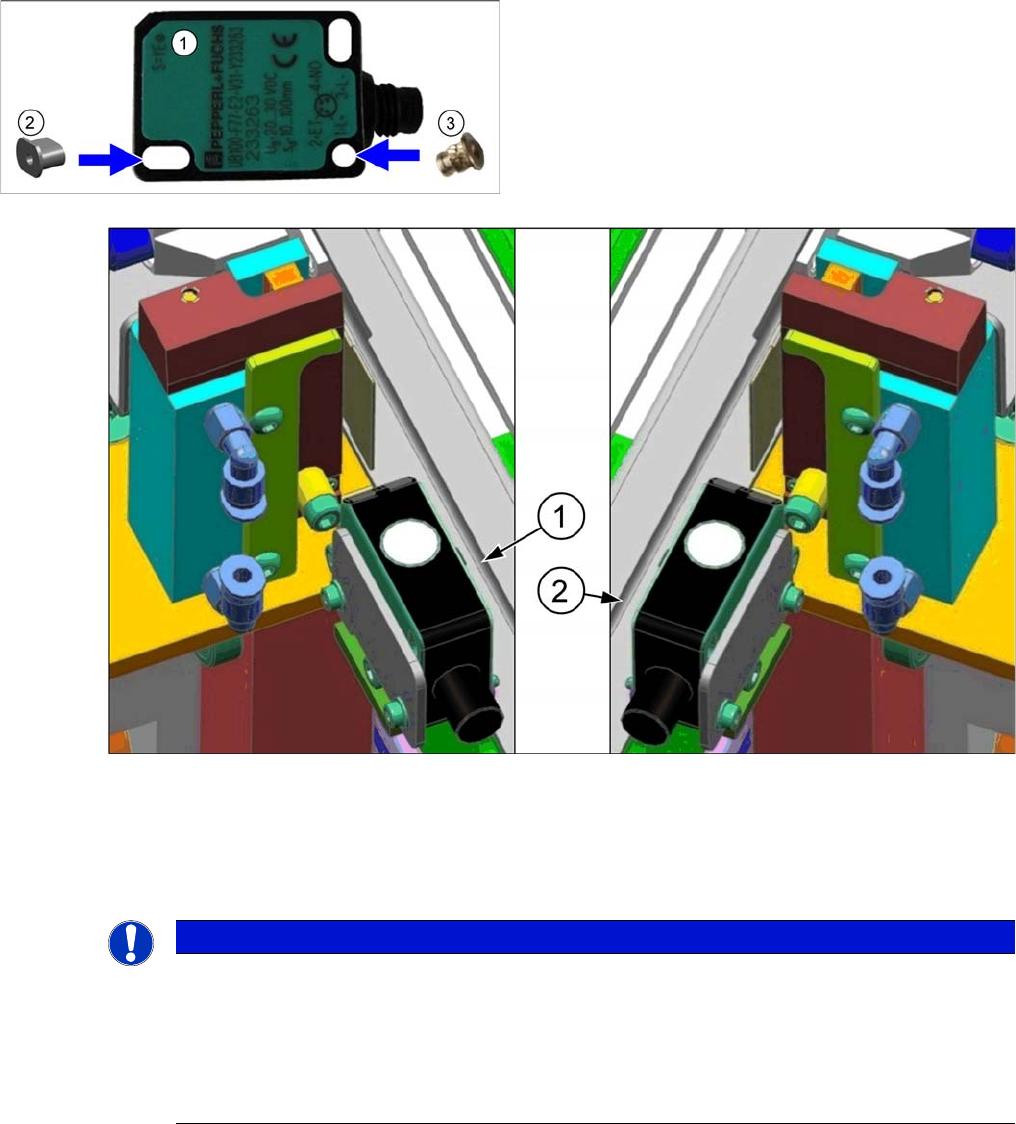
► Insert the sockets into the sensor:
1. For sonar sensors on the sensor rail of the right side, you need to position the sockets on the right,
as viewed from the connection side.
2. For sonar sensors on the sensor rail of the left side, you need to position the sockets on the left, as
viewed from the connection side.
1. Sonar sensor
2. Threaded socket P+F [03096703-xx] (oval)
3. Press-in threaded insert M2 [03088352-xx] (round)
NOTICE
Recommendation: fix socket with adhesive
The sockets do not need to be fixed with adhesive for technical reasons. However, for easier
assembly it may be advisable to fix them like this. This helps to prevent them from falling out or
from the socket being turned with other parts.
► Use suitable adhesive to fix the sockets. It should be designed to bind plastics with metal
e.g. Loctite 401 [00805104-xx].
Service Work
Conveyor 3.6.21 Replacing the Ultrasonic Sensor PXS240 [03069863-xx]
130 Service Manual SIPLACE SX4/DX4
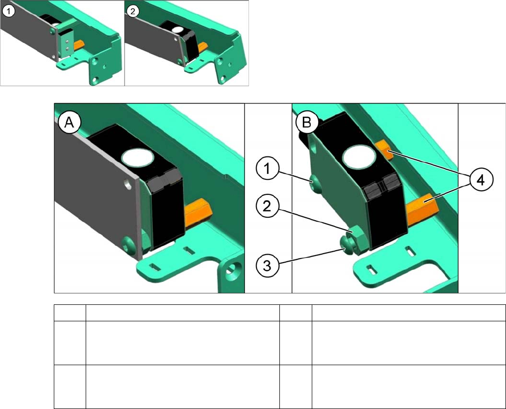
Assembly Differences on the Conversion Board
► Observe the following differences during assembly on the conversion board at the end of PA1 and
at the beginning of PA2:
Functional check
► Perform a function check. If this is not successful, you will need to reteach the sonar sensor. (see
"5.5.2 Teaching the Sonar Sensor PXS240" [ ➙ 256]).
See also
3.6.1 Loosening the Conveyor Side Clamps [ ➙ 95]
1. Assembly of old sonar sensor [03069863-xx]
2. Assembly of new sonar sensor [03089004-xx]
The old sonar sensor is fixed separately behind the con-
version board.
A Diagram with conversion board B Diagram with conversion board hidden
1 Screw M4x16mm
DIN-EN-ISO7380-M3x16-A2-70
[03040340-xx]
2 Nut as spacer
ISO4032-M4-A2-70 [03008166-xx]
3 Screw M4x20mm
DIN-EN-ISO7380-M3x20-A2-70
[03045197-xx]
4 Spacer bolt