SIPLACE-SX4-DX4-用户手册.pdf - 第111页
Service Work 3.6.9 Replacing the Conveyor Drive [03075892-xx] Conveyor Service Manual SIPLACE SX4/DX4 111 ► When y ou remove the conveyo r drive at lo cation 4, m ove the ad ju stment units over to locations 3 and 4, at …
Service Work
Conveyor 3.6.9 Replacing the Conveyor Drive [03075892-xx]
110 Service Manual SIPLACE SX4/DX4
Installation
► Follow the removal instructions in reverse order for installation. Also observe the following instruc-
tions:
3.6.9
3.6.9 Replacing the Conveyor Drive [03075892-xx]
Replacing the Conveyor Drive [03075892-xx]
Parts, equipment and tools
▪ Conveyor drive [03075892-xx]
▪ Belt tension device (00326015-xx)
Overview
Removal
► Use the software to move the conveyor sides into the position which allows you best access. As an
alternative, you can loosen the clamps for the relevant sides in dual conveyors.
► Switch off the machine, disconnect it from the power supply and secure it to prevent unauthorized
reactivation. Observe the instructions in section "1.2 Preparatory Work..." [ ➙ 12].
CAUTION
Installation instructions
► Make sure that the cylinder unit is flush against the carriage. (See also "3.6.6 Replacing the
Cylinder Unit on the Adjustment Unit (DC/QC only)" [ ➙ 106])
► Make sure that you connect the hoses correctly. (See also "3.6.6 Replacing the Cylinder
Unit on the Adjustment Unit (DC/QC only)" [ ➙ 106])
► Make sure that the cables and hoses do not rub against any parts.
► Turn the proximity switch so that the LED is visible when fitted.
► Make sure that the proximity switch does not protrude over the basic structure of the adjust-
ment unit. Check this when the machine is switched on. To do this, move a conveyor side
over the adjustment unit. The LED should only shine when you do this. The gap between
the conveyor side clamping unit and the proximity switch on the adjustment unit must be at
least 0.3 mm.
Check whether this gap is kept for all conveyor sides and that the proximity switch reliably
recognizes all conveyor sides. You can check this with the LED, when the machine is
switched on. Simply move the width adjustment manually along the conveyor with the help
of the toothed belt.
CAUTION
Parallelism
This may affect the parallelism of the width adjustment unit. Bear in mind that this could then
affect the parallelism of the conveyor sides.
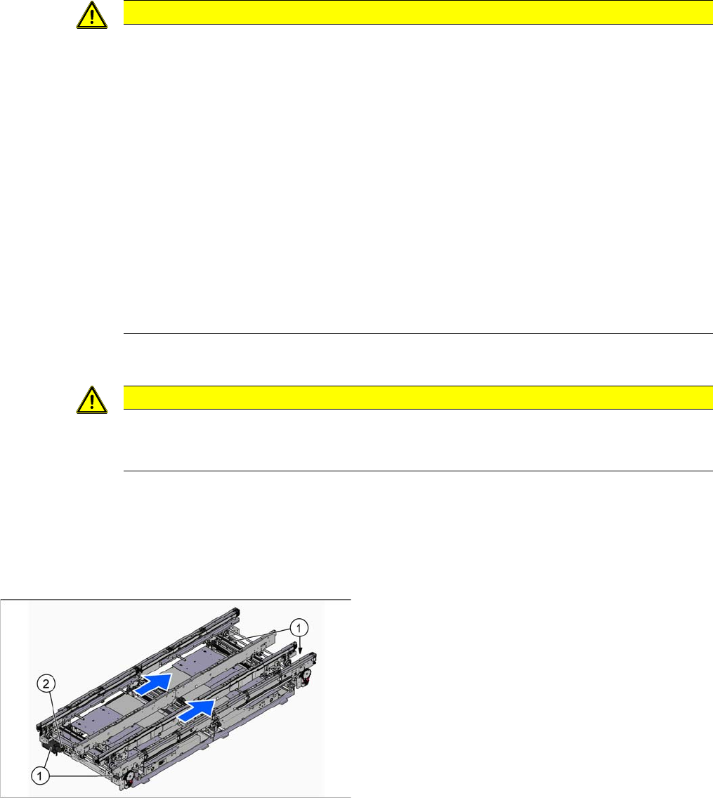
1. Conveyor Drive
2. Width adjustment drive
The width adjustment drive is attached to the convey-
or drive holder near location 4.
Service Work
3.6.9 Replacing the Conveyor Drive [03075892-xx] Conveyor
Service Manual SIPLACE SX4/DX4 111
► When you remove the conveyor drive at location 4, move the adjustment units over to locations 3
and 4, at the side. This makes unintentional maladjustment more difficult. (See "3.6.14 Replacing the
Width Adjustment Toothed Belt [03076223-xx]" [ ➙ 118])
Then loosen the width adjustment belt, giving you access to unthread the width adjustment drive.
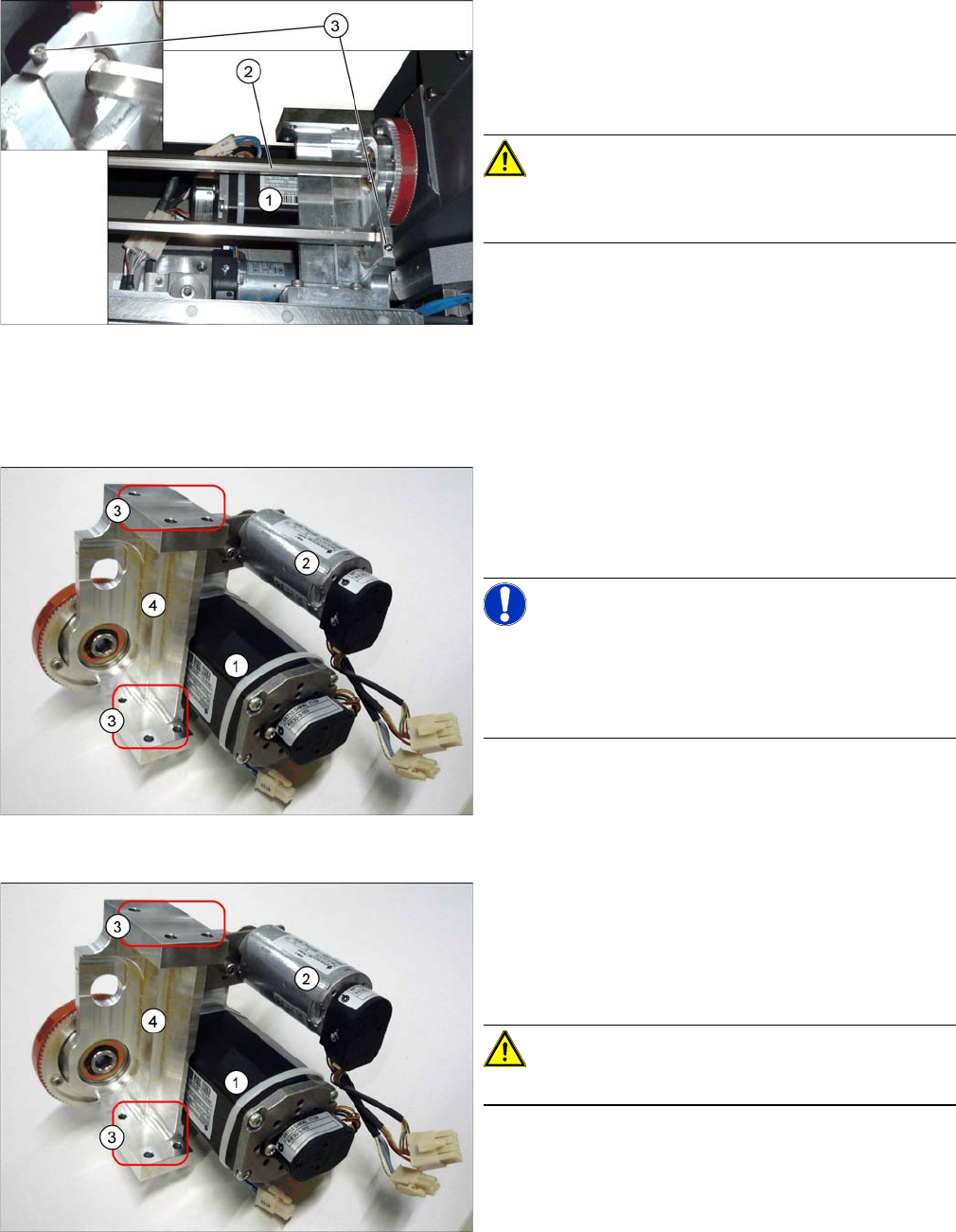
► Loosen the screws (3) fastening the hexagonal shafts
(2) over the conveyor drive (1) and move this drive
carefully within its drilled holes in the machine base.
(See also "3.6.18 Replacing the Hexagonal Shaft
[03057258-xx]" [ ➙ 122])
CAUTION!
There are cables run inside the machine frame.
Make sure you do not damage these cables.
Conveyor drive mount, shown here with the width adjust
-
ment drive
► Unplug the electrical connections to the conveyor
drive (1) and, if present, to the width adjustment
drive (2). Loosen the corresponding cable ties, if re-
quired.
NOTICE!
Single conveyor
You do not need to remove the mount for single convey-
ors, as there is more room next to the conveyor in this
case.
Conveyor drive mount, shown here with the width adjust
-
ment drive
► If the cover plate for the input/output conveyor is fas-
tened to the mount, loosen the relevant fastening
screws.
► Lift the plate slightly upwards to release it from the
mount and then place it down below the conveyor.
CAUTION!
Make sure you do not damage any cables.
Service Work
Conveyor 3.6.9 Replacing the Conveyor Drive [03075892-xx]
112 Service Manual SIPLACE SX4/DX4
Installation
► Follow the removal instructions in reverse order for installation. Also observe the following instruc-
tions:
See also
3.6.1 Loosening the Conveyor Side Clamps [ ➙ 95]
3.6.13 Replacing the Width Adjustment Drive [03078341-xx] [ ➙ 117]
3.6.14 Replacing the Width Adjustment Toothed Belt [03076223-xx] [ ➙ 118]
► Loosen the 3 screws (3) fastening the mount (4) and
then remove the mount and drive carefully from the
machine.
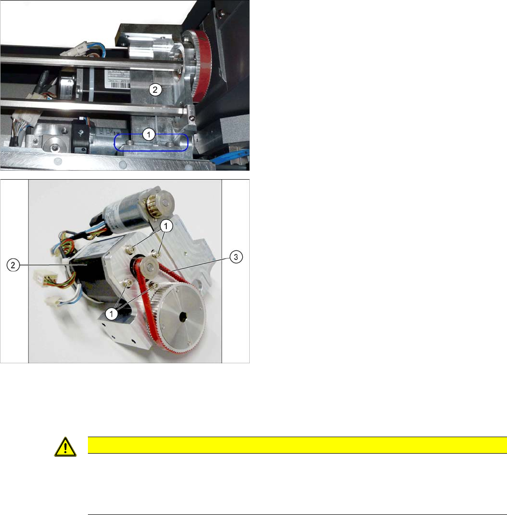
► Loose the 4 screws (1) fastening the conveyor drive
(2). While doing this, carefully unthread the conveyor
drive from the toothed belt (3) and take it off the
mount.
CAUTION
Installation instructions
► Make sure that the toothed belt is positioned accurately in the guidance on the motor shaft.
► While you tighten the screws fastening the conveyor drive, set the tension of the toothed
belt correctly to 250+/-20 Hz.