SIPLACE-SX4-DX4-用户手册.pdf - 第194页
Service Work Docking Station for X-Series C omponent Trolley 3.12.5 Replacing the Positions End Switch of the Component Trolley Locking 194 Service Manual SIPLACE SX4/DX4 3.12.5 3 . 1 2 . 5 R e p la c in g t h e P o s it…
Service Work
3.12.4 Replacing the Locking Lever [03025104-XX] Docking Station for X-Series Component Trolley
Service Manual SIPLACE SX4/DX4 193
3.12.4
3.12.4 Replacing the Locking Lever [03025104-XX]
Replacing the Locking Lever [03025104-XX]
Parts, equipment and tools
▪ Locking lever [03025104-xx]
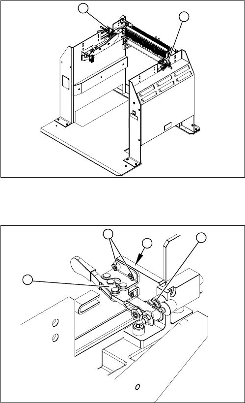
Overview
Removal
Installation
► Loosely screw in the new locking lever.
► Align the locking lever to the edge (3) and tighten the four fastening screws.
► Check that the limit switch (4) is actuated when the locking lever is closed. Correct the position of
the locking lever, where necessary.
► Check the position end switch function, by trying out the locking procedure.
1. Locking lever – on the left side
2. Locking lever – on the right side
1
2
1. Locking lever
2. Four fastening screws
3. Position end switch
► Loosen the four screws (2) (two each at the top and
bottom) fastening the locking lever (1).
► Remove the locking lever.
4
3
2
1
Service Work
Docking Station for X-Series Component Trolley 3.12.5 Replacing the Positions End Switch of the Component Trolley Locking
194 Service Manual SIPLACE SX4/DX4
3.12.5
3.12.5 Replacing the Positions End Switch of the Component Trolley Locking Device [03033395-XX]
Replacing the Positions End Switch of the Component Trolley Locking Device
[03033395-XX]
Parts, equipment and tools
▪ Position end switch [03033395-xx]
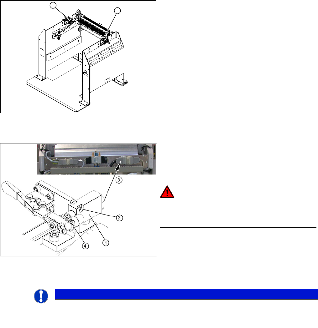
Overview
Removal
► Loosen the two screws fastening the limit switch.
► Open the casing of the connector at the back and label the terminal connections.
► Disconnect the connection cable for the relevant position end switch, in the connector.
► Unthread the connection cable and remove the position end switch.
1. Position end switch – on the left side
2. Position end switch – on the right side
1
2
1. Position end switch with connection cable
2. Two fastening screws
3. Connection cable to connector unit
4. Actuation by locking lever
DANGER!
Switch off the voltage supply
Press the ON/OFF button to switch off and disconnect the
power supply.
NOTICE
Connector for left and right position end switch
► The connection cables for the left and right position end switch are connected to a common
connector.
Service Work
3.12.6 Replacing the 40-Fold Feeder Unlock Device [03011582-xx] Docking Station for X-Series Component Trolley
Service Manual SIPLACE SX4/DX4 195
Installation
► Loosely screw in the new position end switch.
► Run the connection cable to the connector.
► Reconnect the connection cable and close the connector casing.
► Align the position end switch so that the locking lever actuator switches properly.
► Tighten the fastening screws.
► Connect the power pack connection cable and press the ON/OFF button to switch on.
► Check the position end switch function, by trying out the locking procedure.
3.12.6
3.12.6 Replacing the 40-Fold Feeder Unlock Device [03011582-xx]
Replacing the 40-Fold Feeder Unlock Device [03011582-xx]
Parts, equipment and tools
▪ Feeder unlocking device 40-fold [03011582-XX]
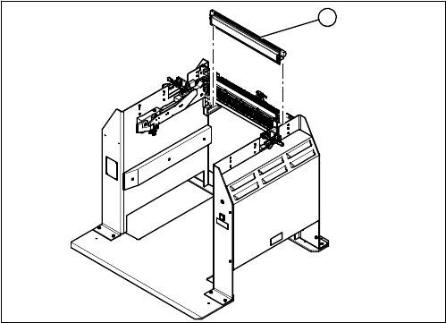
Overview
Removal/installation
The 40-fold feeder unlock device is the same assembly used in the COT insert. The service work is iden-
tical with the procedure used for the COT insert. All necessary service work is described there.
See also
3.10.3 Replacing the 40-Fold Feeder Unlock Device [03011582-xx] [ ➙ 173]
1. 40 fold feeder unlock device
1