SIPLACE-SX4-DX4-用户手册.pdf - 第236页
Settings Gantry Settings 5.4.1 Travel Ranges and Speed Monitoring 236 Service Manual SIPLACE SX4/DX4 5.4 5 . 4 G a n t r y S e t t in g s Gantry Settings 5.4.1 5 . 4 . 1 T r a v e l R a n g e s a n d S p e e d M o n it o…
Settings
5.2.3 Overview of Station Computer Pneumatic Settings
Service Manual SIPLACE SX4/DX4 235
Setting
5.2.3
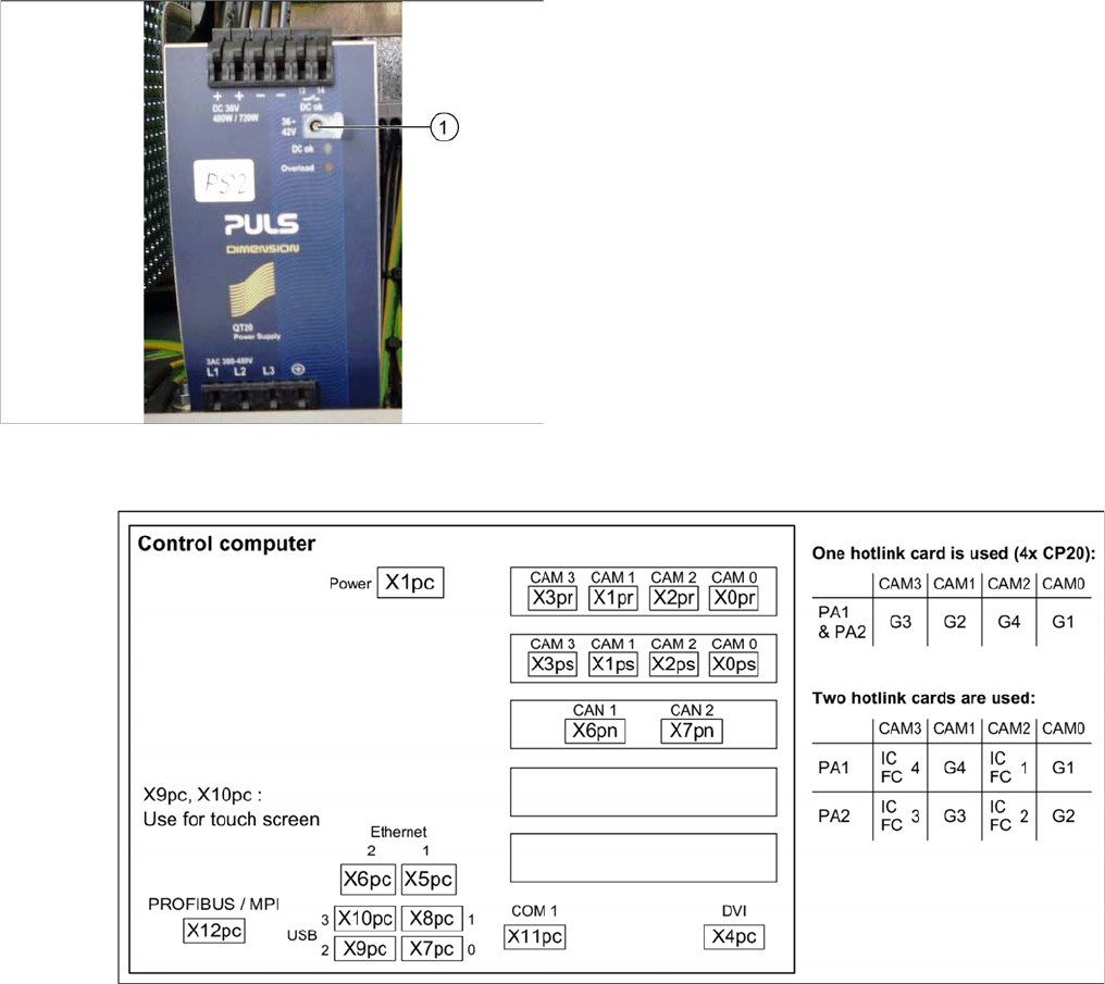
5.2.3 Overview of Station Computer
Overview of Station Computer
See also
6.1.1 I/O control unit [03052315-xx] [ ➙ 271]
5.3
5.3 Pneumatic Settings
Pneumatic Settings
5.3.1
5.3.1 Setting the Compressed Air Controller for Machine Components
Setting the Compressed Air Controller for Machine Components
► Make sure that the compressed air controller for machine components is set to 5.1 bar.
See also
2.7 Pneumatic System [ ➙ 26]
► Open the protective cap on the setting screw (1).
► Use a slotted screwdriver to set the correct voltage on
the pulsed power pack.
Check the voltage with a suitable voltage measuring
device, between the terminals + and –.
Settings
Gantry Settings 5.4.1 Travel Ranges and Speed Monitoring
236 Service Manual SIPLACE SX4/DX4
5.4
5.4 Gantry Settings
Gantry Settings
5.4.1
5.4.1 Travel Ranges and Speed Monitoring
Travel Ranges and Speed Monitoring
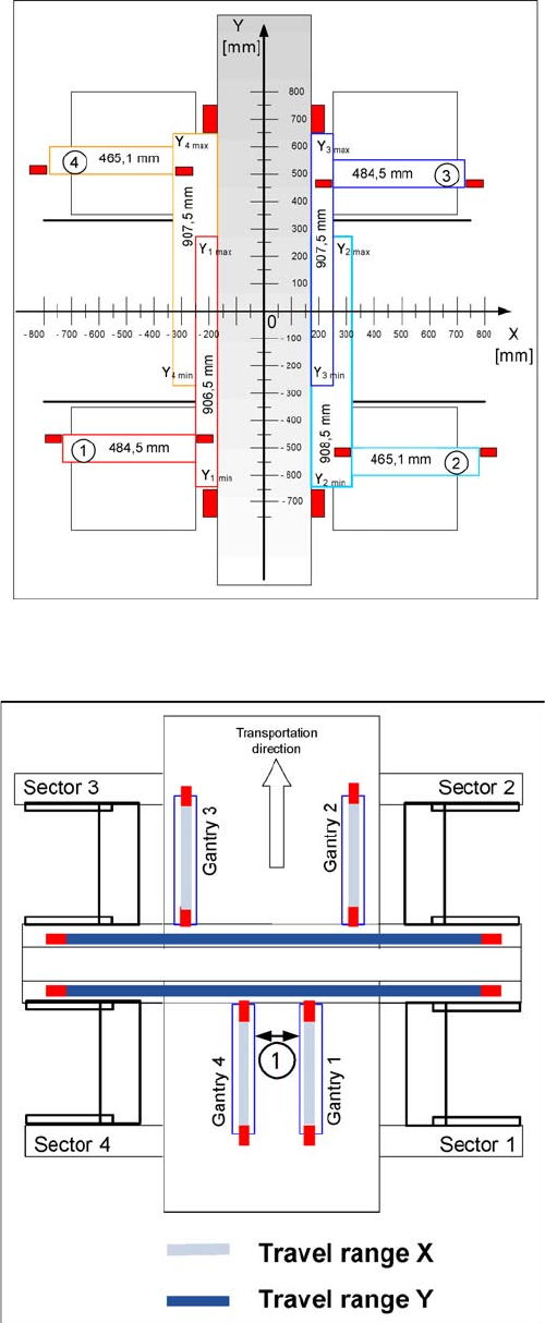
The travel range of the X and Y axes will be determined during machine calibration.
Travel range for X and Y axes (X series shown as exam
-
ple)
1) to 4) = gantry 1 to 4
The end of the X axis travel range is + or - 0.5 mm before
the software limit switch, which is 1.5 mm before the buff-
er. A safety distance of 2.0 mm to the buffer is adequate,
if the X axis moves into this area with excessive speed.
The end of the Y axis travel range is + or - 2.0 mm before
the software limit switch. The Y axis travel range for a
particular placement area is monitored in one direction by
the software limit switch and a buffer. In the other direc-
tion, there is a permanent exchange of communication
between the axes and their positions, via the SPI Bus
(see description of the anticrash function).
Travel range for X and Y axes (X series shown as exam
-
ple)
1. Safety distance between the gantries during place-
ment: minimum 4mm.
Depending on the placement mode (i-placement or alter-
nating), the gantries will operate in one placement area
fully independently. This means that one gantry does not
need to know the position of the other one.
Settings
5.4.2 Error "Gantry Crash" Gantry Settings
Service Manual SIPLACE SX4/DX4 237
5.4.2
5.4.2 Error "Gantry Crash"
Error "Gantry Crash"
A “gantry crash” error is established by calculating the position difference and speed difference for both
axes. A gantry crash error is signaled via the GCUs and the CAN Bus. After the "gantry crash" error mes-
sage has been issued, both gantries need to be referenced.
5.4.3
5.4.3 Count Error:
Count Error:
If the GCU detects a "fatal count error", the axis concerned will be released and the anticrash function
disabled. The other axis is informed of this in the status information and will also disable the anticrash
function. The released axis now needs to be referenced again.
After this, the anticrash function will be re-enabled for both axes.
5.4.4
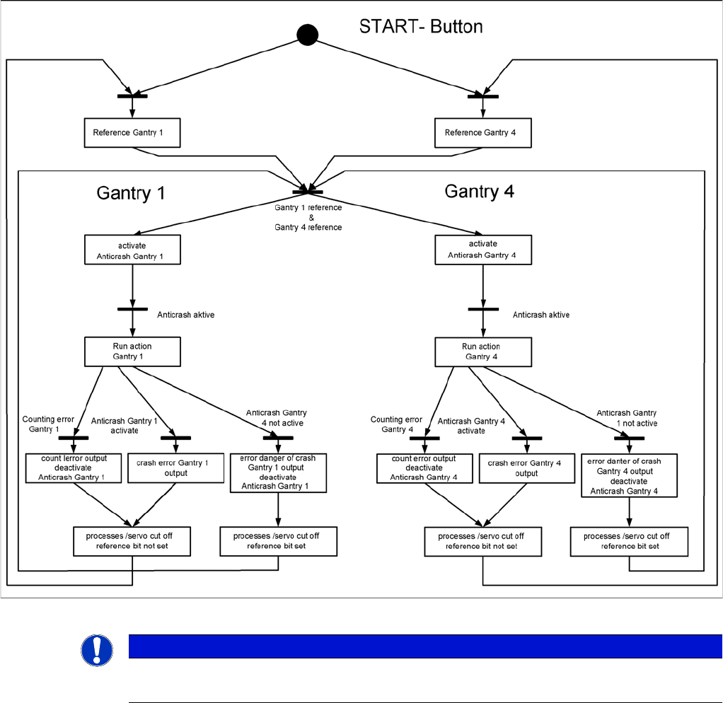
5.4.4 Anticrash Function
Anticrash Function
Example of the anticrash function sequence in placement area 1
NOTICE
GCU, HCU
The GCU and the HCU consist of a control module (axis card) and a power module (servo).