SIPLACE-SX4-DX4-用户手册.pdf - 第91页
Service Work 3.5.12 Replacing the GCU Fan [03060954- xx] Gantries Service Manual SIPLACE SX4/DX4 91 3.5.12 3 . 5 . 1 2 R e p la c in g t h e G C U F a n [ 0 3 0 6 0 9 5 4 - x x ] Replacing the GCU Fan [03060954-xx] Parts…
Service Work
Gantries 3.5.11 Replacing the GCU [03052200-xx]
90 Service Manual SIPLACE SX4/DX4
3.5.11
3.5.11 Replacing the GCU [03052200-xx]
Replacing the GCU [03052200-xx]
Parts, equipment and tools
▪ Positioning control for the gantry axes GCU [03052200-xx]
Overview
Removal
► Switch off the machine, disconnect it from the power supply and secure it to prevent unauthorized
reactivation. Observe the instructions in section "1.2 Preparatory Work..." [ ➙ 12].
► Unplug all connections on the GCU. You may want to mark their positions, to make clear assignment
easier later on.
► Loosen the screws fastening the mount and then remove the mount.
► Remove the GCU from the machine.
Installation
► Follow the removal instructions in reverse order for installation. Also observe the following instruc-
tions:
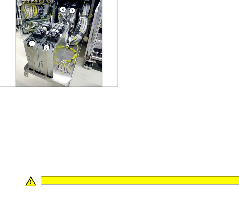
1) to 4) GCUs
The GCUs are located in a rack unit between locations 1
and 2.
The assignment of GCUs to gantries differs according to
the machine type. Observe the instructions in section
"5.4.7 Overview of GCUs" [ ➙ 247].
CAUTION
Installation instructions
► Use the DIP switch to set the gantry ID on the GCU. (see "5.4.7 Overview of GCUs"
[ ➙ 247]).
► Check the firmware and perform a download, if needed. (see "5.8.1 Firmware Download
(SW 70x)" [ ➙ 266]).
Service Work
3.5.12 Replacing the GCU Fan [03060954-xx] Gantries
Service Manual SIPLACE SX4/DX4 91
3.5.12
3.5.12 Replacing the GCU Fan [03060954-xx]
Replacing the GCU Fan [03060954-xx]
Parts, equipment and tools
▪ GCU fan [03060954-xx]
Overview
Removal
► Switch off the machine, disconnect it from the power supply and secure it to prevent unauthorized
reactivation. Observe the instructions in section "1.2 Preparatory Work..." [ ➙ 12].
► Unplug the electrical connection to the fan. You may want to mark the position of this connection, to
make clear assignment easier later on.
► Pull out the four expansion rivets on the fan and then remove the fan.
Installation
► Follow the removal instructions in reverse order for installation. Also observe the following instruc-
tions:
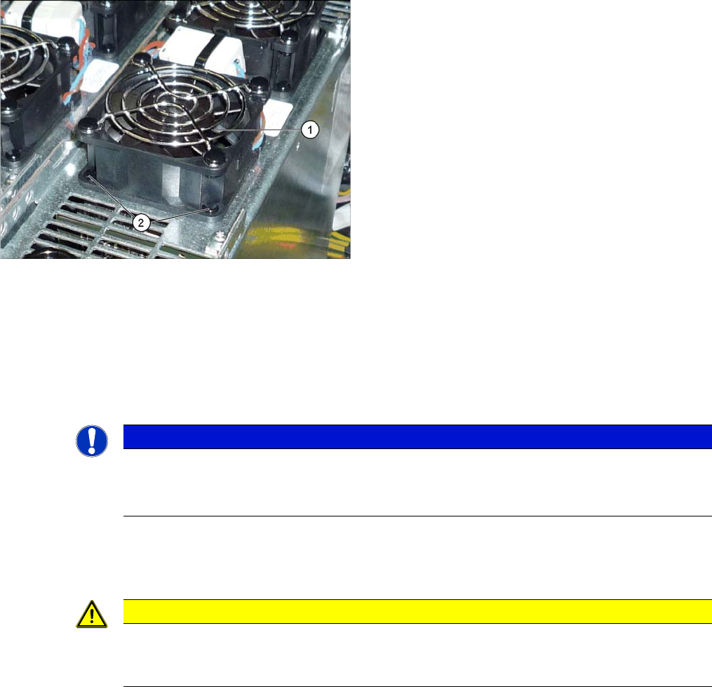
1. Fan on the GCU
2. Plastic expansion rivets
(snap rivet DRM 4x4,5-5.5 sw SR-4070B [03106012-
xx])
These are supplied with the fan.
NOTICE
Two-part expansion rivets
The expansion rivets are in two parts.
► First remove the center pin. The lower part can now be easily pulled out.
CAUTION
Installation instructions
► The expansion rivets are in two parts. First insert the lower part into the hole and then fix
this into place with the upper part.
Service Work
Gantries 3.5.13 Replacing the Head Adapter for the HCU and the HCU
92 Service Manual SIPLACE SX4/DX4
3.5.13
3.5.13 Replacing the Head Adapter for the HCU and the HCU
Replacing the Head Adapter for the HCU and the HCU
Parts, equipment and tools
You can replace either the base adapter alone, the HCU alone or the base adapter together with the
HCU.
The following spare parts/kits can be replaced:
▪ Module X basic adapter C&P [03071420-xx]
Consists of: 1x PCB/X basic adapter C&P [03045647-xx], 1x HCU assembly [03054884-xx]
▪ MHCU assembly compatible [03090990-xx] (replaces: HCU assembly [03054884-xx])
▪ PCB/X base adapter C&P [03045647-xx]
▪ Module/X base adapter TWIN [03062201-xx]
Removal
► Switch off the machine, disconnect it from the power supply and secure it to prevent unauthorized
reactivation. Observe the instructions in section "1.2 Preparatory Work..." [ ➙ 12].
► You may need to dismantle the placement head for
better access. Read the relevant chapter, section
Placement heads, if required.
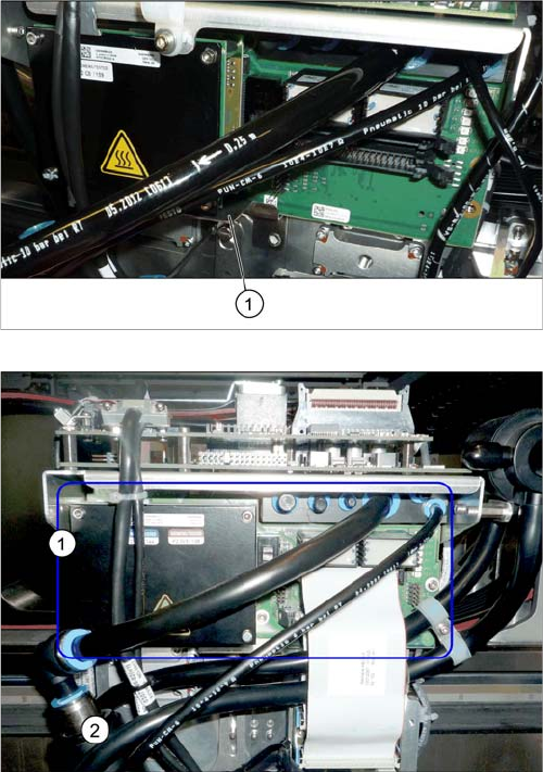
► Loosen the two screws fastening the protective
plate (1) (if present) and remove the protective plate.
Head adapter HCU (example of C&P20A version on an
SX4 shown )
► Unplug all electrical connections to the head
adapter (1). You may want to mark their positions, to
make clear assignment easier later on.