SIPLACE-SX4-DX4-用户手册.pdf - 第36页
Service Work Basic Machine 3.1.4 Guide Rollers on the Covers 36 Service Manual SIPLACE SX4/DX4 3.1.4 3 . 1 . 4 G u id e R o lle r s o n t h e C o v e r s Guide Rollers on the Covers Parts, equipment and tools ▪ Per machi…
Service Work
3.1.3 Replacing the Cover Fan [03056479-xx] Basic Machine
Service Manual SIPLACE SX4/DX4 35
3.1.3
3.1.3 Replacing the Cover Fan [03056479-xx]
Replacing the Cover Fan [03056479-xx]
Parts, equipment and tools
▪ Axial fan type 4414 FNN [03056479-xx]
▪ Sealing varnish Loctite 241 [02101037-xx]
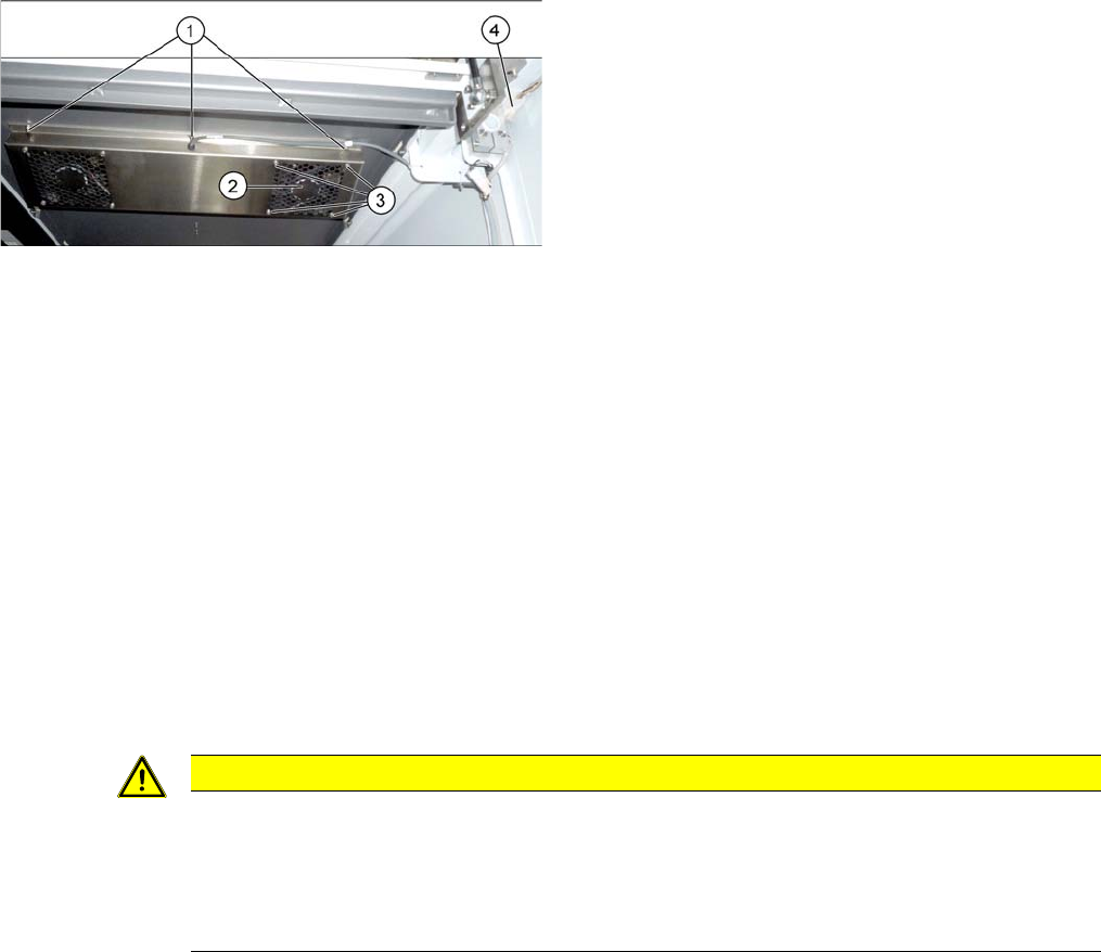
Overview
Removal
► Switch off the machine, disconnect it from the power supply and secure it to prevent unauthorized
reactivation. Observe the instructions in section "1.2 Preparatory Work..." [ ➙ 12].
The fans are fastened to the cover plate, inside. First dismantle the cover plate:
► Loosen and unplug the connection cable (4).
► Loosen the 6 screws fastening the cover plate and remove the cover plate. Make sure that the wash-
ers and contact disks are not lost. You may want to mark their positions, to make clear assignment
easier later on.
► Loosen the four screws fastening the cover fan. Make sure that the washers are not lost.
► Unplug the cover fan connection cable and remove the cover fan from the machine.
Installation
► Follow the removal instructions in reverse order for installation. Also observe the following instruc-
tions:
1. Screws for fastening the cover plate
2. Cover fan
3. Fastening crews for cover fan
4. Connection cable for cover fan
CAUTION
Installation instructions
► When fitting the fan, note the correct direction of the air blown. If necessary, you can use
the adjacent fan as a guide. The direction of air blown is shown by an arrow on the side of
the fan housing.
► Secure the six screws fastening the cover plate with Loctite 241.
Service Work
Basic Machine 3.1.4 Guide Rollers on the Covers
36 Service Manual SIPLACE SX4/DX4
3.1.4
3.1.4 Guide Rollers on the Covers
Guide Rollers on the Covers
Parts, equipment and tools
▪ Per machine:
– 4x roller assembly - pack of 20 [03078561-xx]
– 4x DIN915-M8x16 - pack of 10 [00304354-xx]
or
4x DIN EN ISO4026-M8x16-A2-21H - pack of 10 [03025582-xx]
▪ Open-ended wrench, size 10
▪ Allen key
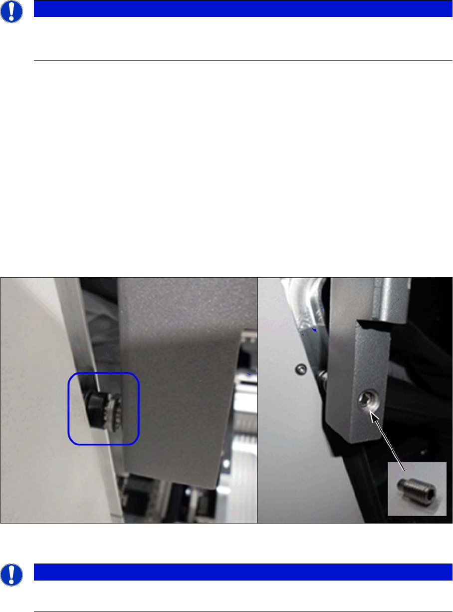
Procedure
► Open the two gantry changer doors and move the covers out of the guidance.
This makes the following work easier.
► Loosen the screwed fixture on the roller (fork wrench size 10). Unscrew as far as required.
► From the inside, screw on a setscrew as lock and tighten it.
Verification
► Check whether the cover can be easily moved along the whole area. Adjust the cover if necessary
(see "5.1.1 Setting the Machine Covers" [ ➙ 227]).
See also
1.2 Preparatory Work... [ ➙ 12]
NOTICE
Example
The following sections are described using the example of an SX1/SX2 machine. The proce-
dure is the same for other machines. Any relevant differences will be mentioned explicitly.
NOTICE
Covering
Between the roller and the guidance there must be at least 75% coverage.
Service Work
3.2.1 Electrical Checks Electrical System
Service Manual SIPLACE SX4/DX4 37
3.2
3.2 Electrical System
Electrical System
See also
2.6 Electrical System [ ➙ 23]
3.2.1
3.2.1 Electrical Checks
Electrical Checks
Please refer to the relevant circuit diagrams when performing electrical checks:
▪ SIPLACE SX4/DX4 detailed circuit diagrams [00196711-xx] (German/English)
3.2.2
3.2.2 Measuring Voltages at the Power Supply Unit
Measuring Voltages at the Power Supply Unit
Tools and Equipment Required
▪ Digital voltmeter, class 1, 5
▪ Test cable with test probes or terminals
Preparation
Voltages
► Measure the required voltages.
Please refer to the relevant circuit diagram for details of the various voltages.
▪ SIPLACE SX4/DX4 detailed circuit diagrams [00196711-xx] (German/English)
DANGER
Observe the safety instructions
There is a risk of dangerous touch voltages and short circuits occurring in power supplies which
have been made accessible and are connected for measurement purposes.
Nonobservance of these safety instructions may cause injury to personnel and damage to the
machine!
Measurements may only be performed by specially trained service technicians, with appropri-
ate qualifications and expertise.
► Observe the instructions in section "1.1.3 Safety Instructions for the Power Supply" [ ➙ 10].
CAUTION
Take care not to damage the supply lines!
Make sure that the main power cable and supply cables in the machine are not trapped and
that the insulation is not damaged.
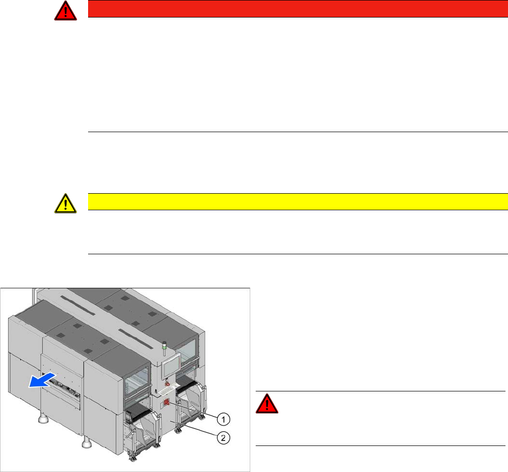
► End all placement operations on the machine.
► Switch the machine off at the main switch (1).
► Disconnect the machine from the main power supply.
► Open the lock on the power supply cover (2).
► Pull the power supply out towards the front.
► Reconnect the machine to the power supply.
DANGER!
Careful: there may be dangerous touch voltages in the vi-
cinity of the open power supply!
► Switch the placement machine on again at the main
switch and start it up.