SIPLACE-SX4-DX4-用户手册.pdf - 第150页
Service Work Placement heads 3.7.6 Replacing Stationary Component Camera Dig i tal Type 25/33/36 150 Service Manual SIPLACE SX4/DX4 3.7.6 3 . 7 . 6 R e p la c in g S t a t io n a r y C o m p o n e n t C a m e r a D ig it…
Service Work
3.7.5 Installation Positions on the Head Plate Placement heads
Service Manual SIPLACE SX4/DX4 149
3.7.5
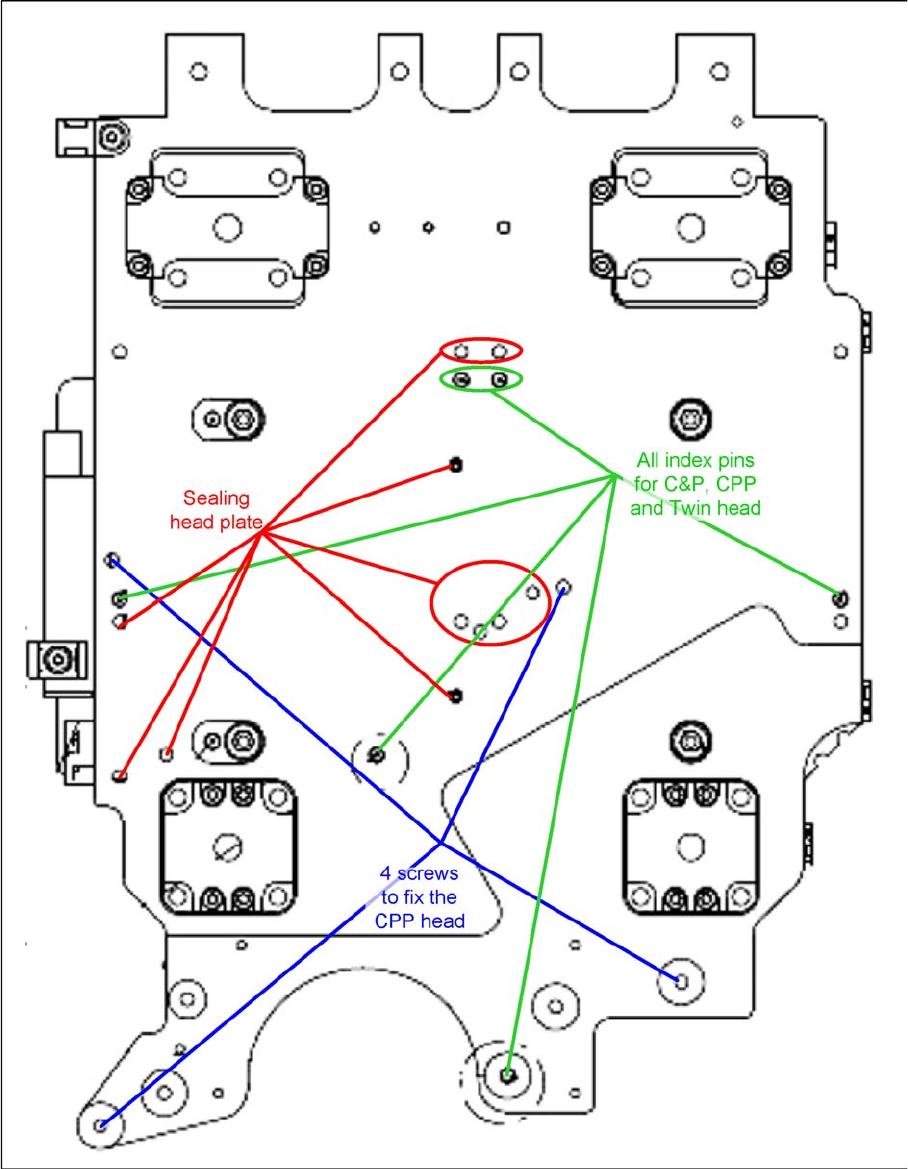
3.7.5 Installation Positions on the Head Plate
Installation Positions on the Head Plate

Service Work
Placement heads 3.7.6 Replacing Stationary Component Camera Digital Type 25/33/36
150 Service Manual SIPLACE SX4/DX4
3.7.6
3.7.6 Replacing Stationary Component Camera Digital Type 25/33/36
Replacing Stationary Component Camera Digital Type 25/33/36
Refer to the appropriate assembly instructions:
X series, SX series, D3 and D1:
▪ Assembly Instructions Stationary Camera 25 (FC) [00194554-xx] (German and English)
▪ Assembly Instructions Stationary Camera Type 33/36 (IC) [00196608-xx] (German and English)
X Series S:
▪ Assembly Instructions Stationary Camera type 25/33 [00197397-xx] (German and English)
See also
5.8.4 DIP Switch for Camera Types 25 and 33 [ ➙ 270]
CAUTION
Risk of injury with cameras of type 25
A heavy mark caul is mounted with the same fixture screws for cameras of type 25. This mark
caul is otherwise only held by the locating pins. If this mark caul falls down, it could cause inju-
ries.
► Make sure that this mark caul is not pulled off the locating pins.
NOTICE
Camera adaptor
You may need to fit an IC camera adaptor assembly. (See the assembly instructions)
► Location 1 to 3: IC camera adaptor assembly SX4a [03099054-xx]
► Location 4: IC camera adaptor assembly SP4 SX4a [03099004-xx]
Service Work
3.7.6 Replacing Stationary Component Camera Digital Type 25/33/36 Placement heads
Service Manual SIPLACE SX4/DX4 151
3.7.6.1
3.7.6.1 Installation Height of the Stationary Camera
Installation Height of the Stationary Camera
The installation height at which the camera can be installed depends on the camera version. You will
either only be able to use one specific height or will have the option of several installation heights. The
following description only applies for the following camera versions with three possible installation
heights:
▪ Stationary component camera P&P (type 33) 55x45 digit. [03016339-xx] from version -06
▪ Stationary component camera P&P (type 36) 32x32 digit. [03042491-xx] from version -04
Stationary Camera in Position 1
Stationary Camera in Position 2
Position 2 is not relevant for the SX and the X series.
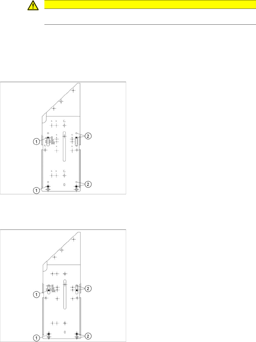
Stationary Camera in Position 3
CAUTION
Head crash danger
An incorrect installation height can result in a head crash!
1. Screw
2. Thread in the machine frame
Position 1 has to be used in the following cases:
▪ SX1/SX2: always
▪ SX4, X series: If at least one DLM or CPP head is
used in the corresponding placement area.
1. Screw
2. Thread in the machine frame
Position 3 has to be used in the following cases:
▪ SX1/SX2: never.
▪ SX4, X series: If only TwinHeads are used in the cor-
responding placement area.