SIPLACE-SX4-DX4-用户手册.pdf - 第133页
Service Work 3.6.25 Replacing the Conveyor Control TSP410 [03076208-xx] Conve yor Service Manual SIPLACE SX4/DX4 133 3.6.25 3 . 6 . 2 5 R e p la c in g t h e C o n v e y o r C o n t r o l T S P 4 1 0 [ 0 3 0 7 6 2 0 8 - …
Service Work
Conveyor 3.6.23 Replacing the Clamping Plate [03081665-xx]
132 Service Manual SIPLACE SX4/DX4
3.6.23
3.6.23 Replacing the Clamping Plate [03081665-xx]
Replacing the Clamping Plate [03081665-xx]
Parts, equipment and tools
▪ Clamping plate assembly [03081665-xx]
▪ Tool for travel limitation [03013650-xx]
Overview
Removal
► Use the software to move the conveyor sides into the position which allows you best access. As an
alternative, you can loosen the clamps for the relevant sides in dual conveyors.
► Switch off the machine, disconnect it from the power supply and secure it to prevent unauthorized
reactivation. Observe the instructions in section "1.2 Preparatory Work..." [ ➙ 12].
Installation
► Follow the removal instructions in reverse order for installation. Also observe the following instruc-
tions:
See also
3.6.1 Loosening the Conveyor Side Clamps [ ➙ 95]
3.6.24
3.6.24 Replacing the Compression Spring on the Clamping Plate [00364715-xx]
Replacing the Compression Spring on the Clamping Plate [00364715-xx]
Parts, equipment and tools
▪ Compression spring 0.63*5.63*26 [00364715-xx]
▪ Tool for travel limitation [03013650-xx]
Removal/installation
► Removal and installation of the pressure spring is the same as that for the clamping plate. (See
"3.6.23 Replacing the Clamping Plate [03081665-xx]" [ ➙ 132])
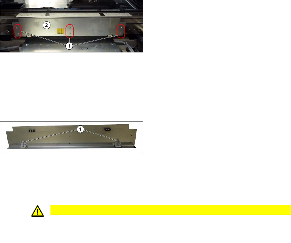
Clamping plate (using example of SX1/SX2)
1. Screws fastening the clamping plate
2. Clamping plate
Clamping plate (using example of SX1/SX2)
► Loosen the 6 screws fastening the clamping plate
and remove the clamping plate. Make sure that you
do not lose the two compression springs (1).
CAUTION
Installation instructions
► Reinsert the compression springs.
► Check the clamping plate for ease of movement.
Service Work
3.6.25 Replacing the Conveyor Control TSP410 [03076208-xx] Conveyor
Service Manual SIPLACE SX4/DX4 133
3.6.25
3.6.25 Replacing the Conveyor Control TSP410 [03076208-xx]
Replacing the Conveyor Control TSP410 [03076208-xx]
Parts, equipment and tools
▪ Conveyor control TSP410 assembly [03076208-xx]
Overview
Removal
► Use the software to move the conveyor sides into the position which allows you best access. As an
alternative, you can loosen the clamps for the relevant sides in dual conveyors.
► Switch off the machine, disconnect it from the power supply and secure it to prevent unauthorized
reactivation. Observe the instructions in section "1.2 Preparatory Work..." [ ➙ 12].
► Loosen the screws fastening the lifting table plate and remove the lifting table plate.
► Loosen the screws fastening the conveyor control cover and push this cover to one side.
► Unplug all electrical connections to the conveyor control. Mark their positions, to make clear assign-
ment easier later on.
► Loosen the screws fastening the conveyor control and remove it from the machine.
Installation
► Follow the removal instructions in reverse order for installation. Also observe the following instruc-
tions:
See also
3.6.1 Loosening the Conveyor Side Clamps [ ➙ 95]
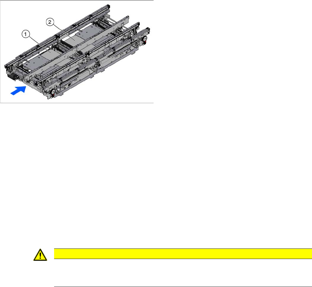
1. TSP410 lane 1 (under the cover)
2. TSP410 lane 2 (under the cover)
For an overview of the connectors, switches etc. of the
TSP410, refer to section "6.3.3 Conveyor control
TSP410" [ ➙ 291].
The single conveyor has one TSP410 fitted (PA1), the
dual and quad lane conveyors each have two.
CAUTION
Installation instructions
► Check the firmware and perform a download, if needed. (See "5.8.1 Firmware Download
(SW 70x)" [ ➙ 266])
Service Work
Placement heads 3.7.1 Fast Head Exchange
134 Service Manual SIPLACE SX4/DX4
3.7
3.7 Placement heads
Placement heads
3.7.1
3.7.1 Fast Head Exchange
Fast Head Exchange
By means of the Fast Head Exchange (FHE) it is possible to replace a placement head within 15 min-
utes.
See also
3.7.3 Replacing the CPP Head [ ➙ 142]
3.7.2 Replacing the C&P20/A/M Head [ ➙ 139]
3.7.1.1
3.7.1.1 Requirements
Requirements
If the following requirements are met, the heads can be replaced using the FHE and are ready for use
after a brief calibration.
▪ Software 702:
The software version 702 only supports replacement of placement heads which have the same type,
i.e., replacing a C&P20A with another C&P20A head or a CPP with another CPP head.
– SW 702 and the current eSW versions
– The placement heads in the machine have the calibration data stored in the EEPROM.
– The "segment offset bottom" for the second head height has been determined by a double meas-
urement of the data.
– A fast head exchange is not possible for a CPP head with a stationary camera.
– A fast head exchange is not possible for the TwinHead.
– The head plate is equipped with a hook and the placement head with the corresponding eyelet.
– Torx screws are used as head screws.
– The screws are undetachably fixed to the head.
– The heads to be fitted must already be equipped with calibration nozzles.
▪ Software 703:
With SW 703 the fast head exchange has been enhanced by the following functions:
– Head and component camera can now be separated on CPP and C&P20A heads.
– A verification is carried out on all SX machines.
– The "segment offset bottom" for the second head height is calculated by interpolation.
– You can use precalibrated heads from the head test rig or the stock.
– C&P20A heads are equipped with a T-piece between the pressure control valve and the return
unit, in order to reduce the number of compressed air connections at the pneumatic distributor.