SM-131-006.pdf - 第101页
0406-001 5- B

Chapter 5
Head Section
This chapter describes how to replace and adjust the head
section.
• Replacement of Head Unit
• Replacement of Linear Measure Sensor
• Replacement of Doughnut Board
• Replacement of Nozzle Shaft
• Location of Each Sensor
• Adjustment of Offsets
• MSB Whole Cleaning and Lubrication Procedures
0605-002 5-A

0406-001 5-B
Device
Name
Chip Mounter
Block Name
Page No.
Unit Name
Revision
Model ItemGXH-1
Chapter 5 Head Section
1. Replacement of Head Unit
1.1 Detachment of Head Unit
If the head unit can be zeroed, the power supply should be shut down at the origin
position.
(Especially the HL axis)
.
1.1.1 Disconnection of Head Cover Wires
(1) Detach the head cover.
(Upper Area on Front Side)
(2) Detach the cover for the linear measure
sensor board (amplifier). (Fig. E1)
CN4 (white 8 pins) on the board must
also be disconnected.
(3) Cut the tie wraps of the camera cable and
the wires for the lighting. (Several Places)
(4) Disconnect the camera cable from the
camera.
(5) Disconnect the nylon connectors (6 pins)
for the lighting wires.
(One of the connectors is covered with
tube (E61).)
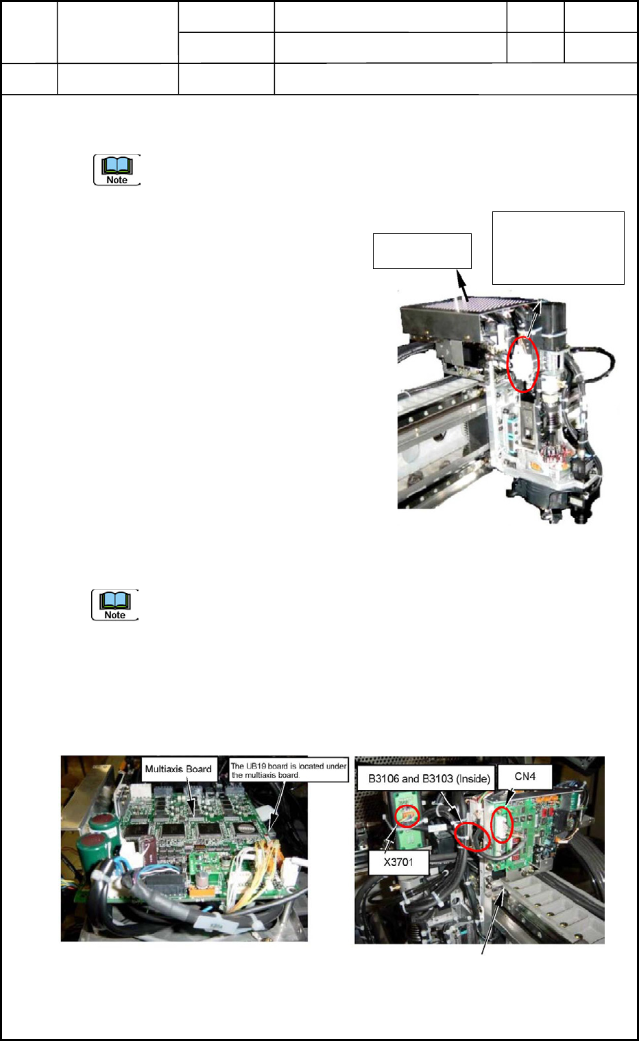
(6) Disconnect two nylon connectors B3106
and B3103 (4 pins).
It is required to detach the multiaxis board because the connectors are located under
the board. (Fig. E2)
When the connectors are not visible, yet after the multiaxis board is etached, it is
also required to detach the UB19 board located under the multiaxis board.
(7) Disconnect the four nylon connectors B3101, B3102, B3104, and B3105. (located
beside the NL Axis)
(8) Disconnect J1 Connector X3701 (6 pins) from the slip ring section.
(9) Detach the two pneumatic pipes.
0406-001
5-1
Head Cover
Connector No.
B3101, B3102,
B3104, B3105
Fig. E1 Head Unit Section
Fig. E2 Head Control Board
Fig. E3 Linear Measure Sensor
Amplifier Board