SM-131-006.pdf - 第156页
Device Name Chip Mounter Block Name Page No. Unit Name Revision Model Item GXH-1 2. Replacement of Backup Base Servoamplifier Chapter 6 Backup Base Section 2.3 Setting of Servoamplifier 2.4 Attachment of Servoamplifier R…
Device
Name
Chip Mounter
Block Name
Page No.
Unit Name
Revision
Model ItemGXH-1
2. Replacement of Backup Base Servoamplifier
Chapter 6 Backup Base Section
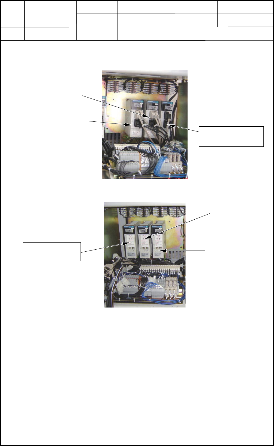
2.1 Location of Servomotor Amplifier (Driver)
2.2 Detachment of Servoamplifier
(1) Disconnect the connectors (CN1A, CN1B, CN2, and CN3) located on the front side
of the servoamplifier.
(2) Detach the power line located under the servoamplifier.
Supply 200 V AC : L1, L2, and L3
Control 200 V AC : L11 and L21
Motor : U, V, W, and PE
(3) Detach the servoamplifier from the panel. (fastened by screws)
Cutter Axis A63 in Section A
Cutter Axis A63 in Section B
NA Section
Backup Axis A53
Fig. F7 Side 1 below Main Body (BA Block)
Cutter Axis A63 in
Section D
Cutter Axis A63 in
Section C
NC Section
Backup Axis A53
Fig. F8 Side 3 below Main Body (BC Block)
0406-001
6-4
Device
Name
Chip Mounter
Block Name
Page No.
Unit Name
Revision
Model ItemGXH-1
2. Replacement of Backup Base Servoamplifier
Chapter 6 Backup Base Section
2.3 Setting of Servoamplifier
2.4 Attachment of Servoamplifier
Refer to "2.2" and "2.3" on previous pages for details.
Note the connection of the wires.
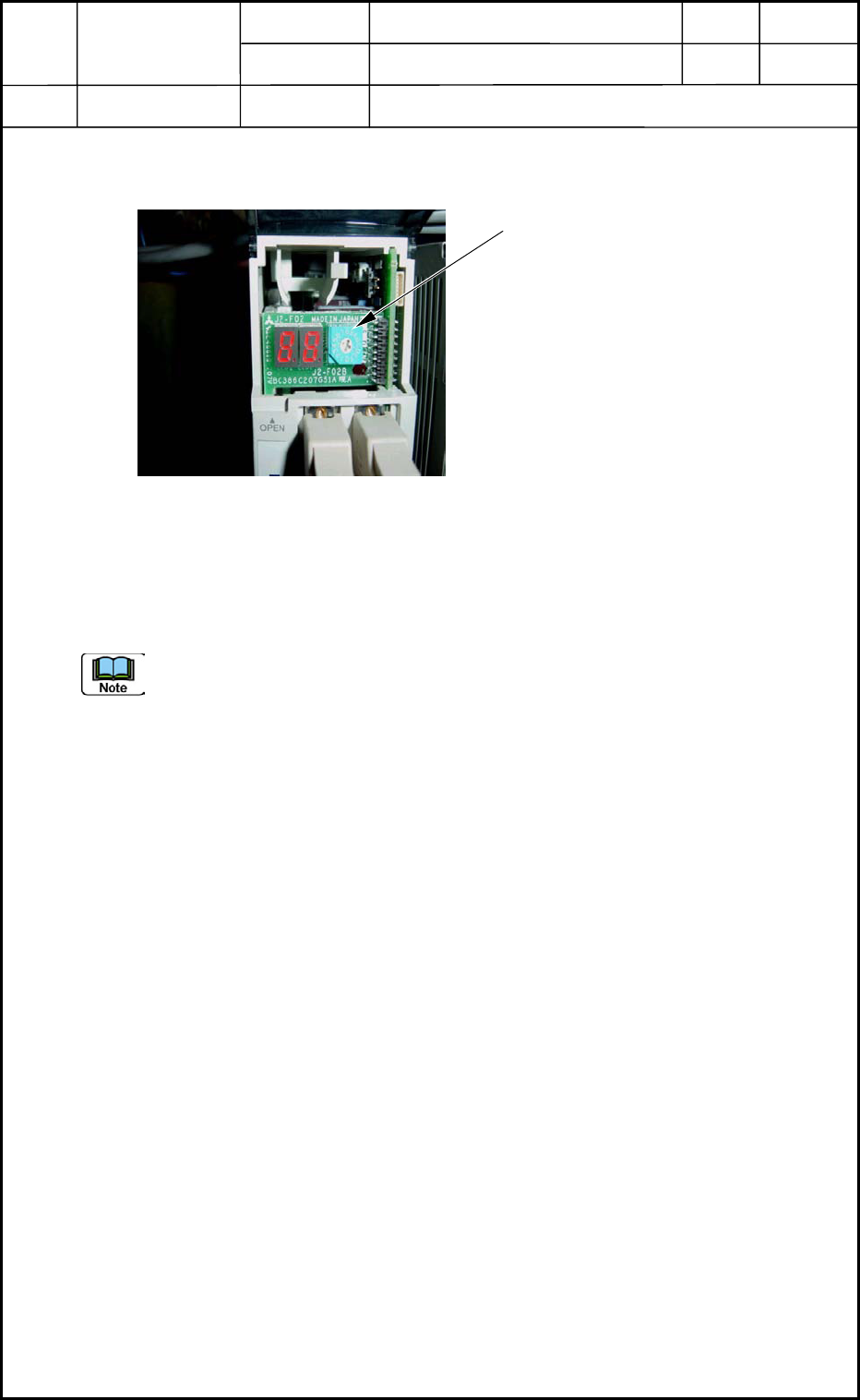
Fig. F9 Front Cover Opened
Axis Selection Switch
Set the address.
NA (A53) Transfer A Backup
NA (A53) Transfer C Backup
ADDRESS: 5 for Both
0406-001
6-5
Device
Name
Chip Mounter
Block Name
Page No.
Unit Name
Revision
Model ItemGXH-1
3. Backup Base Sensor Position
Chapter 6 Backup Base Section
3.1 Backup U/D and Lower Limit Detection
Confirm with a photosensor checker and a dial gauge that the backup U/D and lower limit
detection sensor is changed to "E/R" (Light Emitted and Received) mode from "E/NR"
(Light Emitted and Not Received) mode at the position where the backup base has
ascended by 1.0±0.2 mm after the brake was released, the backup base was moved down,
and the base touched the stopper.
• When "E/NR" is not changed to
"E/R" at the position, make the
adjustment with Pin 10.
After the setting of the lower limit
detection, confirm that Phase C can be
detected in the range where the backup
base ascends 1.8 to 2.2 mm from the
position where the lower limit
detection sensor is turned "ON".
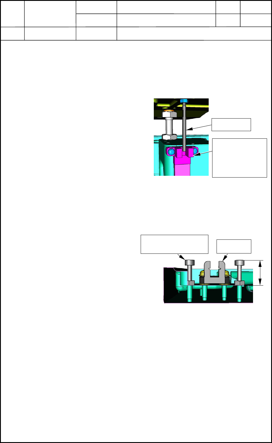
3.2 Setting of Protective Stopper for Backup Base Detection Sensor
(1) Attach Backup Base Detection
Sensor S26 to the backup base.
(Small Pan-Head Screw M3L10)
(2) Loosen the M3 nuts and adjust the
height of the stopper bolts (M3L16)
so that the dimension between the
bolt mounting face and the bolt
head can be "14.5±0.2 mm" as
shown in Fig. F11.
Fig. F10 Backup U/D and Lower Limit
Detection
Pin 10
Backup U/D and
Lower Limit
Detection Sensor
S27
14.5±0.2
Stopper Bolt (M3L16)
and Nut (M3)
S26
Fig. F11 Protective Stoppers
0406-001
6-6