SM-131-006.pdf - 第64页
Device Name Chip Mounter Block Name Page No. Unit Name Revision Model Item GXH-1 2.3.2 Component Recognition Camera Offs et (Execution of Offset Teaching Operation) Required Jigs : Component Recognition Offset Jig JG-008…
Device
Name
Chip Mounter
Block Name
Page No.
Unit Name
Revision
Model ItemGXH-1
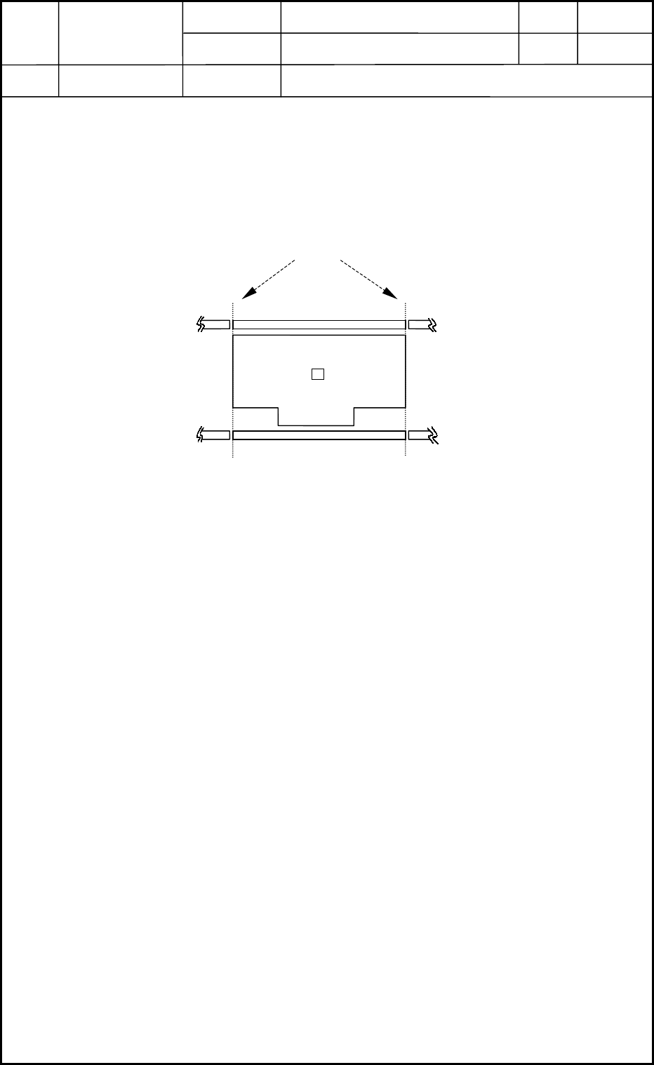
(3) Set up the glass jig PCB.
After setting up the conveyor width, place the glass jig PCB on the
positioning center by hand.
Be sure to align the glass jig PCB with the outer edges of the center
conveyor. (See Fig. A8.)
(4) Make the glass jig PCB clamped.
Open the "ADJUSTMENT" window and select the [Stage #1] or the
[Stage #2] button. (Operation Sequence: [OPERATOR] Button →
[MAINT.] Button → [DVC CHECK] Button → [ADJUST] Button).
Select the [Inp/Pos PCB] button in the "P.C.B. transfer" group box.
Press the [START] button. The clamping is completed.
• When the [START] button is pressed after the [Out PCB] button, the
clamping is released.
• Procedure for Teaching Operation
(1) Select one of the [1], [2], [3], and [4] buttons in the "camera/beam select" group box of
the "RECOG CAMERA & BEAM OFFSET" window. (Operation Sequence: [MAINT.]
Button → [TEACHING] Button → [OTHERS] Button → [PEC RECOG & BM OFST]
Button)
Select the [Use] button in the "Glass jig" group box.
Select the [Teach Start] button and press the [START] button to start the teaching
operation.
(2) Follow the same procedure for "[1] through [4]" in the "camera/beam select" group box.
(3) Select the [End] button.
The "Confirmation to Saving" dialog box opens. Select the [Yes] button.
The teaching session is terminated.
⇒Conveyor
Machine Reference Side
Conveyor
Jig PCB
Fig. A8 Position of Glass Jig PCB
Stage 1
Stage 2
Outer Edges of Center Conveyor
Heads
2. Installation Offset
1-10
0403-001

Device
Name
Chip Mounter
Block Name
Page No.
Unit Name
Revision
Model ItemGXH-1
2.3.2 Component Recognition Camera Offset (Execution of Offset Teaching
Operation)
Required Jigs : Component Recognition Offset Jig JG-0085 (Standard Accessory Part)
Nozzle for Jig Pickup φ6 mm (Nozzle Type HA09)
• Procedure for Teaching Operation
(1) Put the jig on the jig depository.
(Left Front Side of Component Recognition Camera: Sides 1 and 4, Right Front Side:
Sides 2 and 3)
(2) Attach the vacuum nozzle to the Nozzle No. 1 position.
(3) Select one of the [1], [2], [3], and [4] buttons in the "Select camera" group box of the
"COMPONENT RECOG CAMERA OFFSET" window and confirm that "1" is set in the
"Nozzle No." text box in the "Designate Nozzle" group box. (Operation Sequence:
[MAINT.] Button → [TEACHING] Button → [OTHERS] Button → [CMP RECOG
CAMR OFST] Button)
(4) Select the [Teach Start (Offset Data)] button and press the [START] button.
(5) Follow the same procedure for "[1] through [4]" in the "Select camera" group box.
(6) Select the [End] button.
The "Confirmation to Saving" dialog box opens. Select the [Yes] button.
The teaching session is terminated.
As "0.04°" is set for "Pick-up difference tol Angle [deg]", the teaching operation
is automatically repeated the number of the specified times until the difference
becomes less than "0.04°".
Heads
2. Installation Offset
1-11
0403-001

Device
Name
Chip Mounter
Block Name
Page No.
Unit Name
Revision
Model ItemGXH-1
2.3.3 Teaching of Head Center/Basis Mark Position Offsets
Required Jig : Component Recognition Offset Jig JG-0085 (Standard Accessory Part)
Nozzle for Jig Pickup φ6 mm (Nozzle Type HA09)
After teaching the head center offset, be sure to perform a teaching operation on the basis
mark position offset.
• Procedure for Teaching Operation
(1) Put the jig on the jig depository.
(Left Front Side of Component Recognition Camera: Sides 1 and 4, Right Front Side:
Sides 2 and 3)
(2) Attach the vacuum nozzle to the Nozzle No. 1 position.
(3) Select one of the [1], [2], [3], and [4] buttons in the "Select head" group box of the
"HEAD CENTER/BASIS MARK POSITION OFFSET" window and confirm that "1" is
set in the "Nozzle No." text box in the "Designate Nozzle" group box. (Operation
Sequence: [MAINT.] Button → [TEACHING] Button → [OTHERS] Button → [HEAD
CNTR/MARK POS] Button)
(4) Select the [Teach Start (Hd center teach)] button and press the [START] button.
(5) After the teaching operation on the head rotational center, save the results.
(6) Perform a teaching operation on the basis mark position offset as follows.
Select the [Teach Start (Basis mark teach)] button and press the [START] button.
(7) Follow the same procedure for "[1] through [4]" in the "Select head" group box.
(8) Select the [End] button.
The "Confirmation to Saving" dialog box opens. Select the [Yes] button.
The teaching session is terminated.
2.3.4 Fly Recognition Camera Offset
(1) Select one of the [1], [2], [3], and [4] buttons in the "Select camera" group box of the
"FLY RECOG CAMR OFST" window. (Operation Sequence: [MAINT.] Button →
[TEACHING] Button → [OTHERS] Button → [FLY RECOG CAMR OFST] Button)
(2) Select the [Teach Start] button and press the [START] button.
(3) Select the [End] button.
The "Confirmation to Saving" dialog box opens. Select the [Yes] button.
The teaching session is terminated.
Heads
2. Installation Offset
1-12
0406-002