SM-131-006.pdf - 第195页
0406-001 10-B

Chapter 10
Nozzle Stocker Section
This chapter describes how to replace and adjust the nozzle
stocker section.
• Replacement of Nozzle Stocker Unit
• Setting of Nozzle Stockers, Sensors, and Solenoid Valves
0406-001 10-A

0406-001 10-B
Device
Name
Chip Mounter
Block Name
Page No.
Unit Name
Revision
Model ItemGXH-1
Chapter 10 Nozzle Stocker
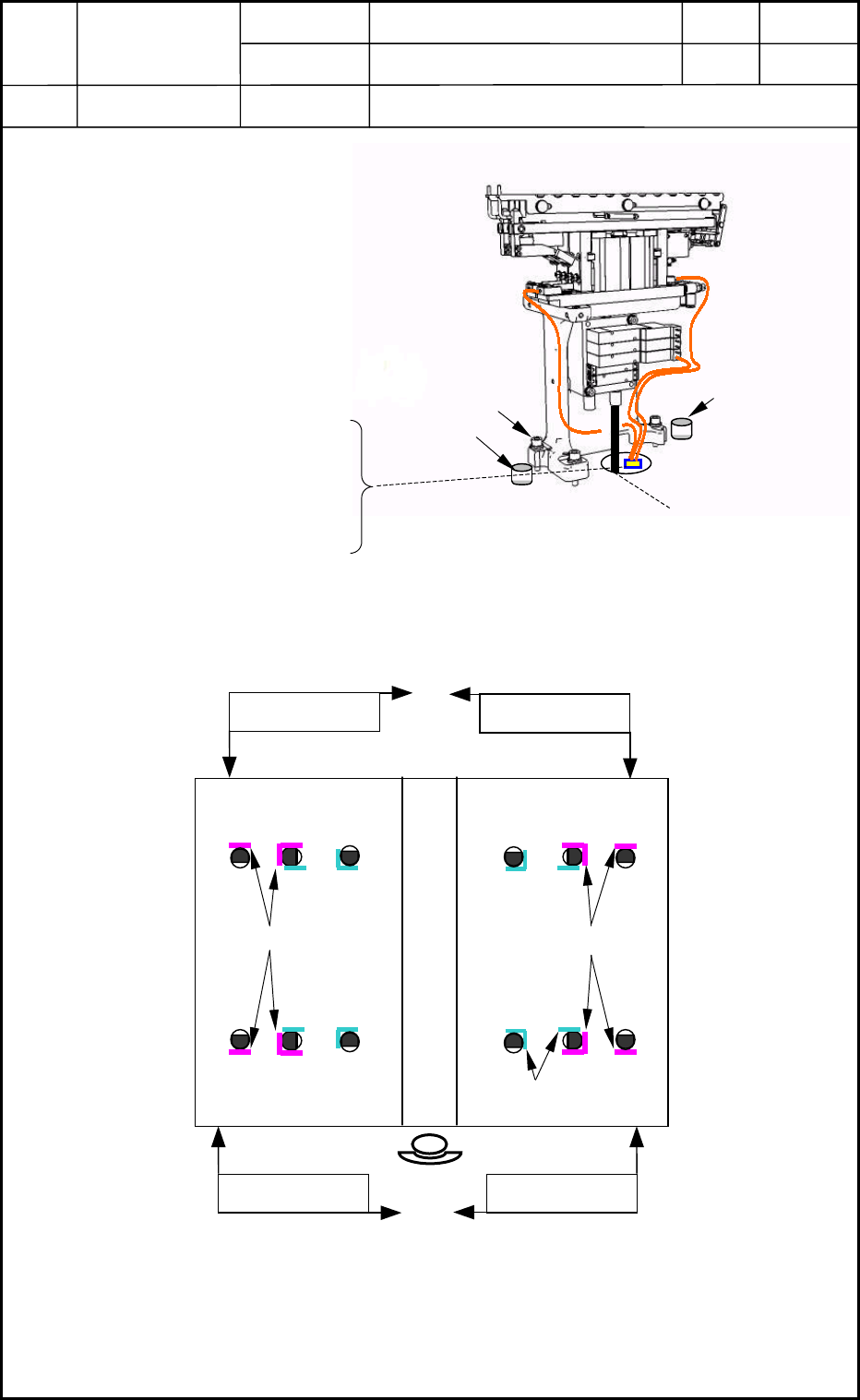
1. Replacement of Nozzle Stocker Unit
M6L25 3
p
cs.
Positioning Pin
Positioning Pin
Air Pipe
•
Nylon Connector (6-Pin) 1 pc.
(Solenoid Valve)
• Nylon Connector (4-Pin) 6 pcs.
(Sensor)
Fig. J1 Nozzle Stocker Unit
1.1 Detachment of Nozzle Stocker Unit
(1) Disconnect the air pipe and the
nylon connector. (Fig. J1)
(2) Remove the three bolts (M6L25)
from the main machine and detach
the nozzle stocker unit. (Fig. J1)
1.2 Attachment of Nozzle Stocker Unit
(1) ● shows the location of a positioning pin and the arrows the pushing directions for the
attachment of the nozzle stocker unit (Fig. J2)
(2) Connect the air pipe and electric wires. (Fig. J1)
(3) Attach the nozzle stocker unit to the main machine.
0406-001
10-1
Component Recognition
Camera Positions
Nozzle Stocker
Piti
Pushing Direction
Fig. J2 Positioning of Nozzle Stockers
Pushin
g
Direction
Nozzle Stocker
Piti
Pushin
g
Direction Pushin
g
Direction