SM-131-006.pdf - 第197页
Device Name Chip Mounter Block Name Page No. Unit Name Revision Model Item GXH -1 Chapter 10 Nozz l e Stocker Section 2. Setting of Nozzle Stockers, Sens ors, and Solenoid Valves 2.1 Location of Sensor s and Solenoid Val…
Device
Name
Chip Mounter
Block Name
Page No.
Unit Name
Revision
Model ItemGXH-1
Chapter 10 Nozzle Stocker
1. Replacement of Nozzle Stocker Unit
M6L25 3
p
cs.
Positioning Pin
Positioning Pin
Air Pipe
•
Nylon Connector (6-Pin) 1 pc.
(Solenoid Valve)
• Nylon Connector (4-Pin) 6 pcs.
(Sensor)
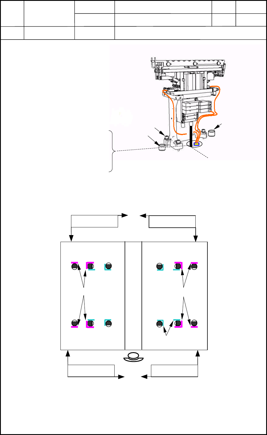
Fig. J1 Nozzle Stocker Unit
1.1 Detachment of Nozzle Stocker Unit
(1) Disconnect the air pipe and the
nylon connector. (Fig. J1)
(2) Remove the three bolts (M6L25)
from the main machine and detach
the nozzle stocker unit. (Fig. J1)
1.2 Attachment of Nozzle Stocker Unit
(1) ● shows the location of a positioning pin and the arrows the pushing directions for the
attachment of the nozzle stocker unit (Fig. J2)
(2) Connect the air pipe and electric wires. (Fig. J1)
(3) Attach the nozzle stocker unit to the main machine.
0406-001
10-1
Component Recognition
Camera Positions
Nozzle Stocker
Piti
Pushing Direction
Fig. J2 Positioning of Nozzle Stockers
Pushin
g
Direction
Nozzle Stocker
Piti
Pushin
g
Direction Pushin
g
Direction
Device
Name
Chip Mounter
Block Name
Page No.
Unit Name
Revision
Model Item GXH-1
Chapter 10 Nozzle Stocker Section
2. Setting of Nozzle Stockers, Sensors, and Solenoid Valves
2.1 Location of Sensors and Solenoid Valves
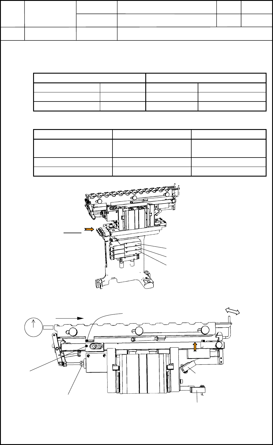
• Solenoid Valves (Fig. J3)
Production Models Experimental Modes - Up to No. 10 Machines
Shutter Opening -Y0935 -Y0936 Stocker 1
Stocker Ascent 1 -Y0936 -Y0937 Stocker 2
Stocker Ascent 2 -Y0937 -Y0935 Shutter
• Sensors (Fig. J4)
Stocker 1 Stocker 2
Unit Lower Limit
Detection
-B0918 -B0919
Shutter Closing Check -B0920 -B0921
Clamping Check -B0922 -B0923
View A
-Y0935
-Y0936
-Y0937
Fig. J3 Nozzle Stocker Solenoid Valves
Clam
p
Lever
Ma
g
net
Shutter O
p
enin
g
G
Cylinder Stroke Adjustment C
Shutter Closing Check
Sensor (B0920,B0921)
Nozzle Clamping Check
Sensor (B0922,B0923)
Nozzle Stocker Unit Lower Limit
Detection Sensor (B0918,B0919)
View B
Fig. J4 Nozzle Stocker Section
0406-001
10-2
Device
Name
Chip Mounter
Block Name
Page No.
Unit Name
Revision
Model ItemGXH-1
Chapter 10 Nozzle Stocker
2. Setting of Nozzle Stockers, Sensors, and Solenoid Valves
2.2 Adjustment of Each Nozzle Stocker Section
2.2.1 Setting of Nozzle Stocker Sensors
• Nozzle Stocker Unit Lower Limit Detection Sensor
Check that the emitted light cannot be received at the lower limit and can be received at the
upward movement.
• Nozzle Stocker Clamping Check Sensor
When a thickness gauge (0.3 mm) is inserted at the place (View B) in Fig. J4, the sensor
receives the emitted light ("Light Emitted and Received" Mode).
At the normal clamping, confirm that the emitted light is not received ("Light Emitted and
Not Received" Mode).
• Shutter Closing Check Sensor
Confirm that the sensor is changed from "ON" to OFF" after the shutter was moved 1 to 2
mm.
2.2.2 Adjustment of Nozzle Stocker Opening Stroke
Lock Cylinder Stroke Adjustment C in Fig. J4 at the position where the shutter is moved back
0.3 mm from the opening-blocked area with the shutter being open.
(Wrench 5.5 2 pcs. and Screw Lock 1401)
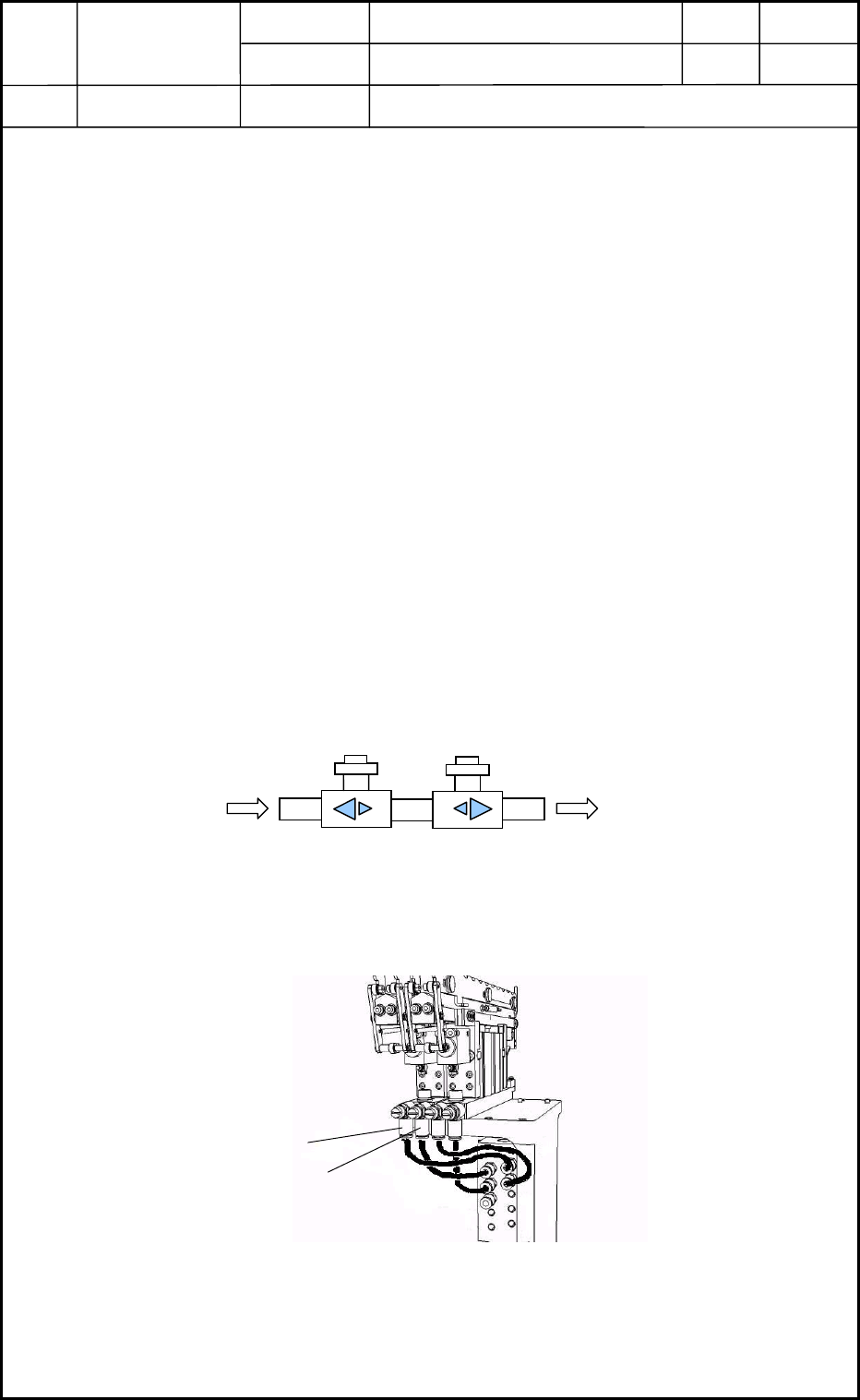
2.2.3 Adjustment of Nozzle Stocker Opening (Shutter) Speed
2.2.4 Adjustment of Nozzle Stocker Ascending Speed
0406-001
10-3
From the shutter valve
To the distribution joint
Fig. J5 Speed Controller
Ascent
Fig. J6 Stocker Ascent/Descent Adjustment Section
Descent