SM-131-006.pdf - 第143页
Device Name Chip Mounter Block Name Page No. Unit Name Revision Model Item GXH -1 Chapter 5 Head Section 7. MSB W hole Cleaning and Lubricat ion Procedures (27) Apply DAPHNE EPONEX No. 1 grease to the top block section c…
Device
Name
Chip Mounter
Block Name
Page No.
Unit Name
Revision
Model Item GXH-1
Chapter 5 Head Section
7. MSB Whole Cleaning and Lubrication Procedures
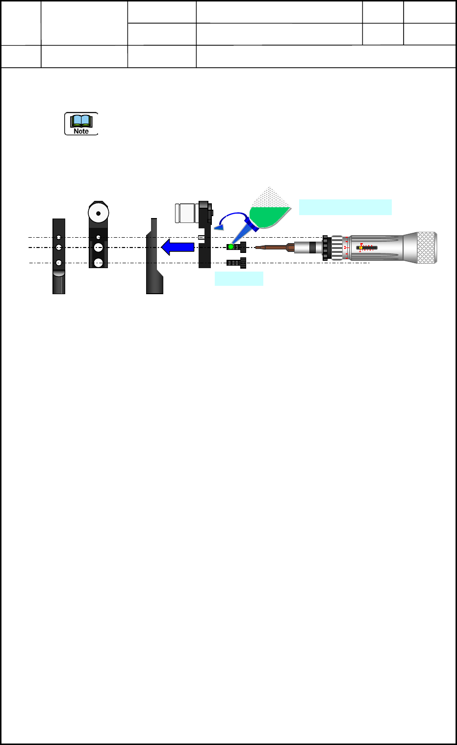
(26) Attach the top blocks <Fig. E75> to the 12-nozzle shafts each section with 2-M1.6×L3
bolts.
- Replace 24-M1.6×L3 bolts with the new one. Please dispose of the old bolts.
(Carefully attach the bolts not to drop them.)
- Set (return) the top blocks to the former positions without any mistake by the No..
- Apply the screw lock (Three Bond 1401B) slightly and tighten it with a tightening
torque (Torque Driver) by 7.5 cNm (0.76 kg f cm).
Fig. E75
0605-001
5-41
Front View
Side View
M1.6
×
L3
Three Bond 1401B
Device
Name
Chip Mounter
Block Name
Page No.
Unit Name
Revision
Model Item GXH-1
Chapter 5 Head Section
7. MSB Whole Cleaning and Lubrication Procedures
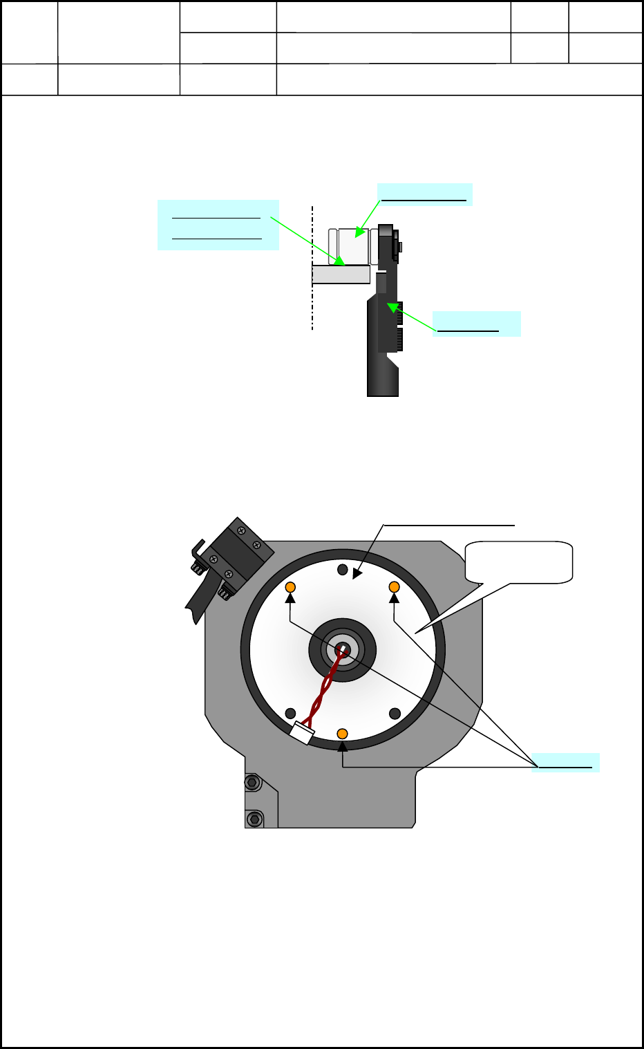
(27) Apply DAPHNE EPONEX No. 1 grease to the top block section cam follower and travel
surface thinly. <See Fig. E76>
Fig. E76
(28) Detach the head section attaching jig (a lid for preventing jumping out nozzle shaft).
Fig. E77
Com Follower
Travel Surface
Cam Follower
To
p
Block
Side View
No. 1 Nozzle Position
View of Head Bottom Surface
No.1 ノズル
No.1
M1.6×L4
Head section
Attaching Jig
0605-001
5-42
Device
Name
Chip Mounter
Block Name
Page No.
Unit Name
Revision
Model Item GXH-1
Chapter 5 Head Section
7. MSB Whole Cleaning and Lubrication Procedures
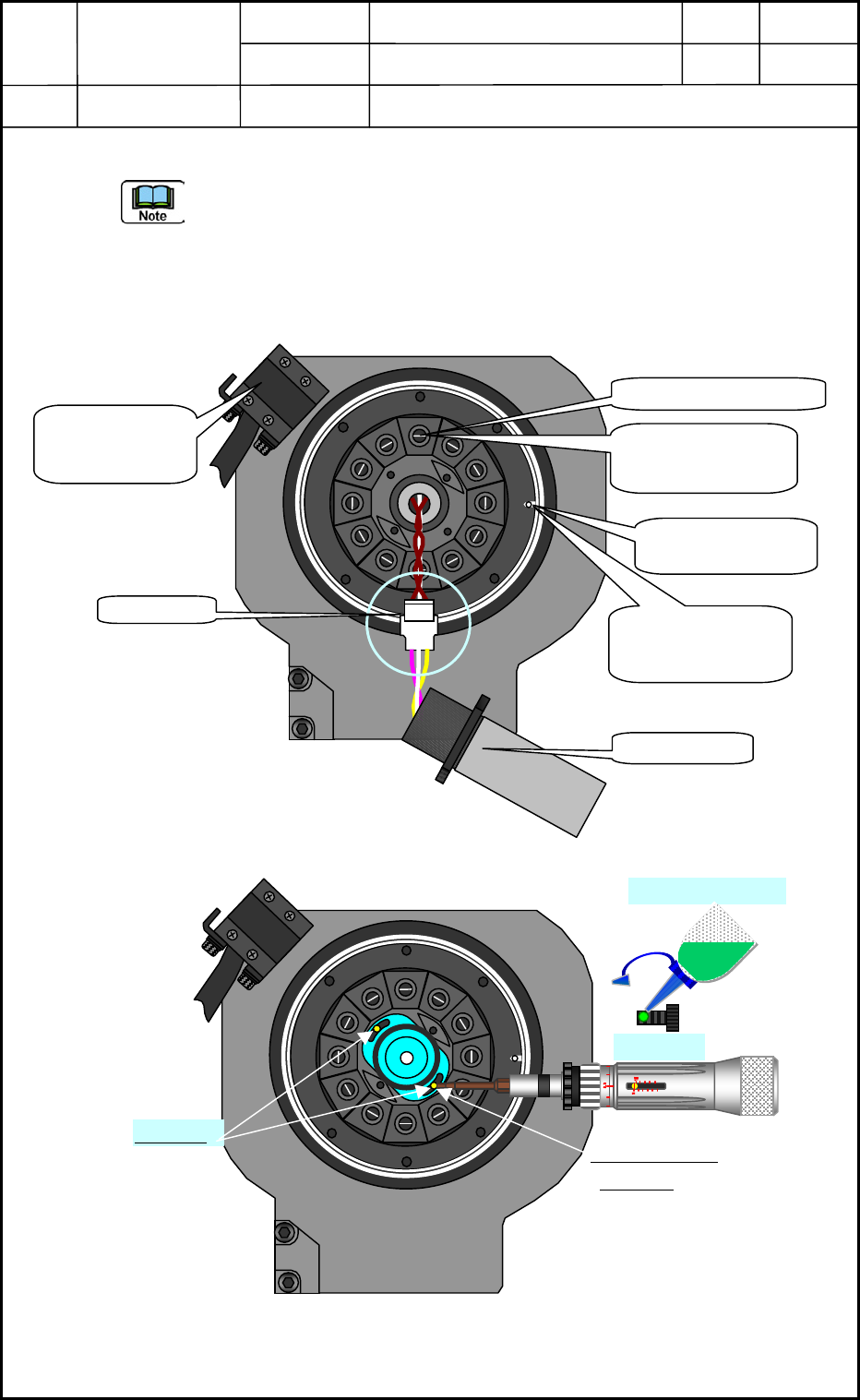
(29) Attach the linear measure sensor emission side.
- Attaching direction of the linear measure sensor: Turn the “white mark” <shown in Fig.
E78> to the light receiving side when the poison is the origin.
- Fixating position of the linear measure sensor: Fix it at the center of the slit shown in
Fig. E79.
- Replace the 2-M1.6×L4 bolts with new one and dispose of the old bolts.
- Apply the screw lock (Three Bond 1401B) to the M1.6×L4 slightly and tighten it with
a tightening torque (Torque Driver <See Fig. E79>) by 7.5 cNm (0.76 kg f cm).
Fig. E78
Fig. E79
M1.6×L4
M1.6×L4
Three Bond 1401B
Center Position
of the slit
View of Head Bottom Surface
Connector
White Mark
Positioning Pin
(Origin Position)
Linear Measure
Sensor Light
Receiving Side
No. 1 Nozzle Position
Direction: At 3:00
o’clock by clock
position
Direction: Just at
12:00 o’clock by
clock
p
osition
View of Head Bottom Surface
0605-001
5-43