SM-131-006.pdf - 第120页
Device Name Chip Mounter Block Name Page No. Unit Name Revision Model Item GXH-1 Chapter 5 Head Section 5. Location of Each Sensor 5.3 Nozzle Position Selection Detection Sensor See Figs. E40 and E41. Fig. E40 Nozzle Pos…
Device
Name
Chip Mounter
Block Name
Page No.
Unit Name
Revision
Model ItemGXH-1
Chapter 5 Head Section
5. Location of Each Sensor
5.2 Location of HL-Axis Sensors and Stoppers
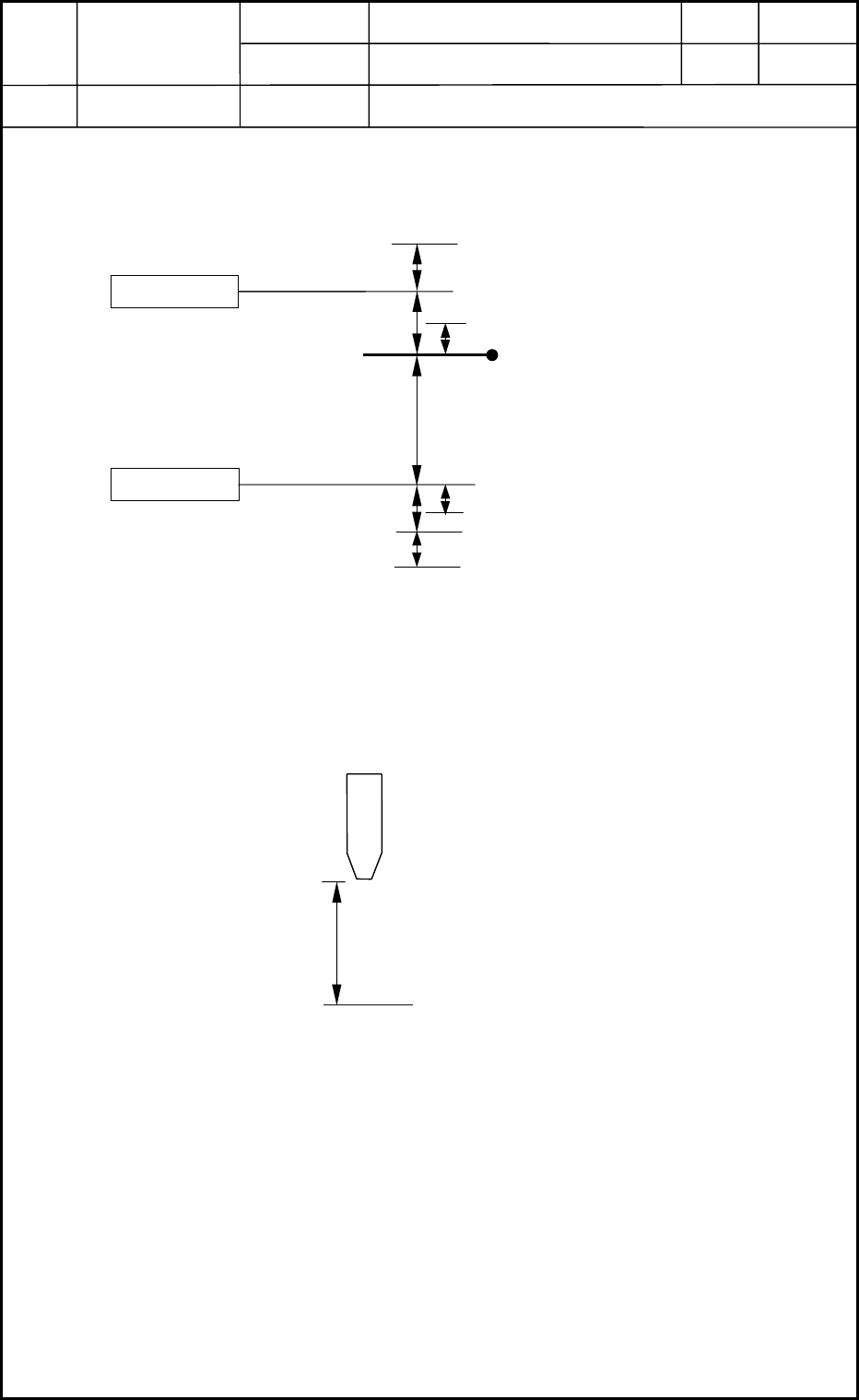
• HL-Axis Origin Position (Referential Value)
(1) Confirm that the NL-axis origin adjustment is already finished.
(2) Loosen the HL-axis coupling and adjust the stoke so that it can be "32±0.05 mm" as
shown below after the HL axis is zeroed.
Fig. E38 Head Level Axis
Photosensor
B3103
B3106
(-) Limit Sensor
(-) Mechanical Stopper
(+) Mechanical Stopper
(+) Limit Sensor
HL-Axis Origin
(mm)
24.0
1 ± 0.1
1
(0.5)
((-) Soft Limit)
((+) Soft Limit)
(0.5)
1 ± 0.2
1
HL-Axis Basic Stroke
Master Nozzle
(NL- and HL-Axis Origin Position)
Fig. E39 HL-Axis Origin Position
Design Value of Stroke: 32 mm
PCB Upper Surface Reference Point
0406-001
5-18
Device
Name
Chip Mounter
Block Name
Page No.
Unit Name
Revision
Model ItemGXH-1
Chapter 5 Head Section
5. Location of Each Sensor
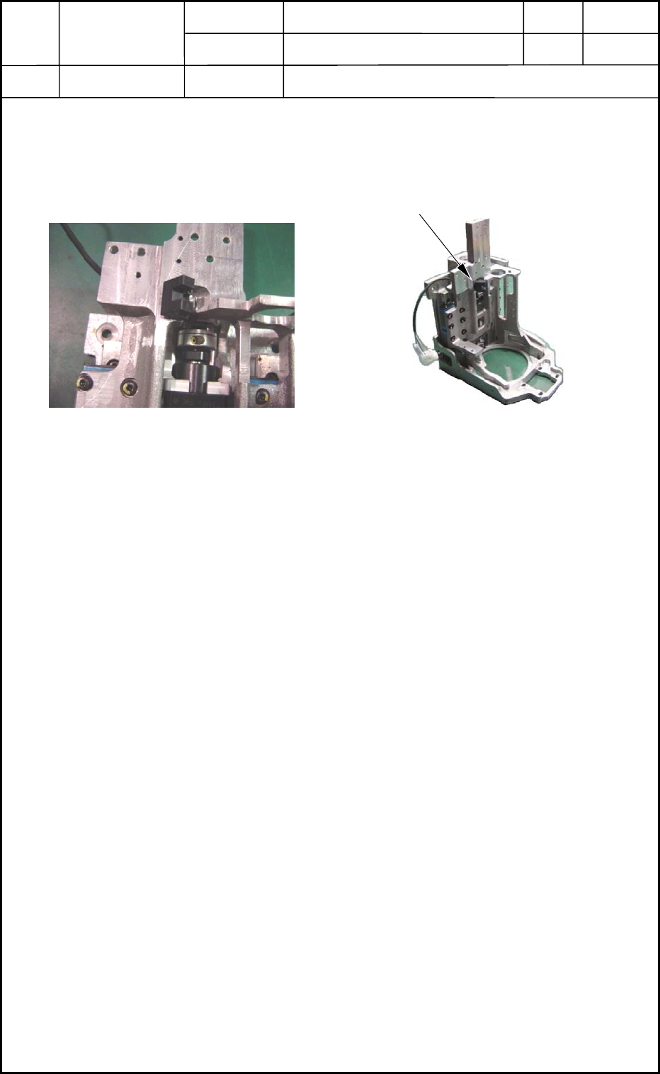
5.3 Nozzle Position Selection Detection Sensor
See Figs. E40 and E41.
Fig. E40 Nozzle Position Selection
Detection Sensor
Fig. E41 Location of Nozzle Position
Selection Detection Sensor
Nozzle Position Selection Detection Sensor
0406-001
5-19

Device
Name
Chip Mounter
Block Name
Page No.
Unit Name
Revision
Model ItemGXH-1
Chapter 5 Head Section
6. Adjustment of Offsets
6.1 Order of Offset Adjustments
Order of Offset Adjustments Procedure for Replacement
Delivery, Transfer, and
Installation
Head Unit
Nozzle Assembly
PEC Recognition Camera
Linear Head Scale
X/Y Motor
Component Recognition
Camera
Nozzle Up/Down Offset 1 1 1 --- --- 2 ---
Feeder (A) Offset L: Up/Down 2 2 2 --- --- 3 ---
Feeder (B) Offset (Manual
Alignment of Pickup Position)
10 11 10 4 8 11 ---
Nozzle Position Offset 8 9 8 --- 6 9 ---
Nozzle Level Offset 9 10 9 --- 7 10 ---
PEC Recognition Camera & Beam
Offset
5 5 --- 1 2 5 ---
6652361
--- --- --- --- --- --- ---
Component Recognition Camera
Offset Teaching
Magnification Teaching
Lighting Teaching
--- --- --- --- --- --- ---
Head Rotational Axis Offset --- 7 6 --- 4 7 2
Head Center/Mark Position 7 8 73583
Fly Recognition Camera Offset --- --- --- --- --- --- ---
Feeder Base Feeder (A) Offset --- --- --- --- --- --- ---
Master Nozzle Level Offset 3 3 3 --- --- 4 ---
NL-Axis Origin Offset 4 4 4 --- --- --- ---
Table Offset --- --- --- --- --- --- ---
Y-Axis Origin Offset --- --- --- --- 1 1 ---
Nozzle Stocker Offsets --- --- --- --- --- --- ---
0406-001
5-20