SM-131-006.pdf - 第203页
Device Name Chip Mounter Block Name Page No. Unit Name Revision Model Item GXH-1 Chapter 11 Recognition Section 1. Replacement of PEC Recognition Camera (5) Remove the three bolts (M4L16) and detach the camera unit from …
Device
Name
Chip Mounter
Block Name
Page No.
Unit Name
Revision
Model ItemGXH-1
Chapter 11 Recognition Section
1. Replacement of PEC Recognition Camera
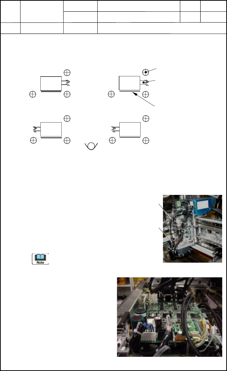
1.1 Directions of PEC Recognition Cameras
(Cameras and Lighting Units) for Detachment
Top View
1.2 Detachment of PEC Recognition Camera Unit
(1) Detach the head cover. (Upper Area on Front Side)
(2) Cut the tie wraps of the camera and lighting cables. (Several Places)
(3) Disconnect the camera cable from the camera.
(4) Disconnect the nylon connector (6 pins) for the
lighting cable.
Detach the multiaxis board to expose the nylon
connector (X13901) located under the multiaxis
board for the head upper section on the main
machine side and disconnect the connector.
When the connector cannot be found after the
detachment of the multiaxis board, try to detach
the UB25 board located under the multiaxis
board.
0406-001
11-1
Setbolt for Camera Attachment
M4 L15 3 places
Lighting Cable
1
3
2 4
Label
Fig. K1 Directions of PEC Recognition Cameras
Camera
Camera
Camera
Camera
Fig. K2 Head Unit
(2)
(3)
Fig. K3 Head Control Board
Device
Name
Chip Mounter
Block Name
Page No.
Unit Name
Revision
Model ItemGXH-1
Chapter 11 Recognition Section
1. Replacement of PEC Recognition Camera
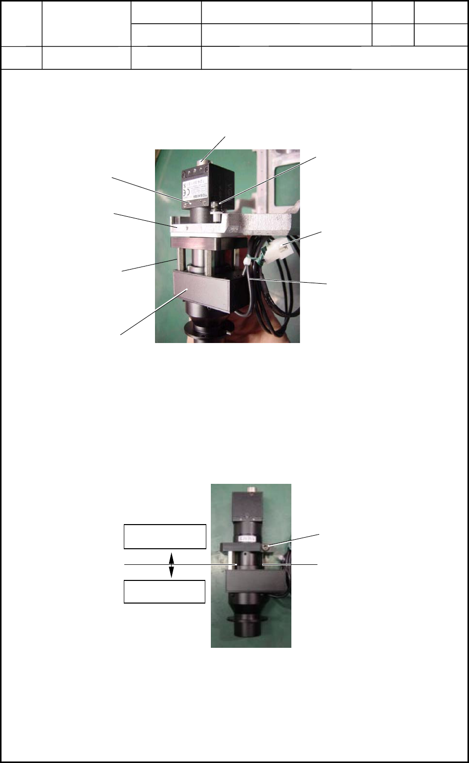
(5) Remove the three bolts (M4L16) and detach the camera unit from the outer frame.
(Fig. K4)
1.3 Detachment of PEC Recognition Camera
(1) Remove the bolt.
(2) Detach the three supports in Fig. K4.
(3) Detach the camera and lighting sections.
Lighting Section
6-Pin
Nylon Connector
M4 L16
Lighting Cable
Fig
Camera Section
Fig. K4 PEC Recognition Camera Unit Section
Outer Frame
Support
Camera Cable Connecting Area
Fig. K5 PEC Recognition Camera and Lighting Sections
Camera Section
Lighting Section
Bolt
0406-001
11-2
Device
Name
Chip Mounter
Block Name
Page No.
Unit Name
Revision
Model ItemGXH-1
Chapter 11 Recognition Section
1. Replacement of PEC Recognition Camera
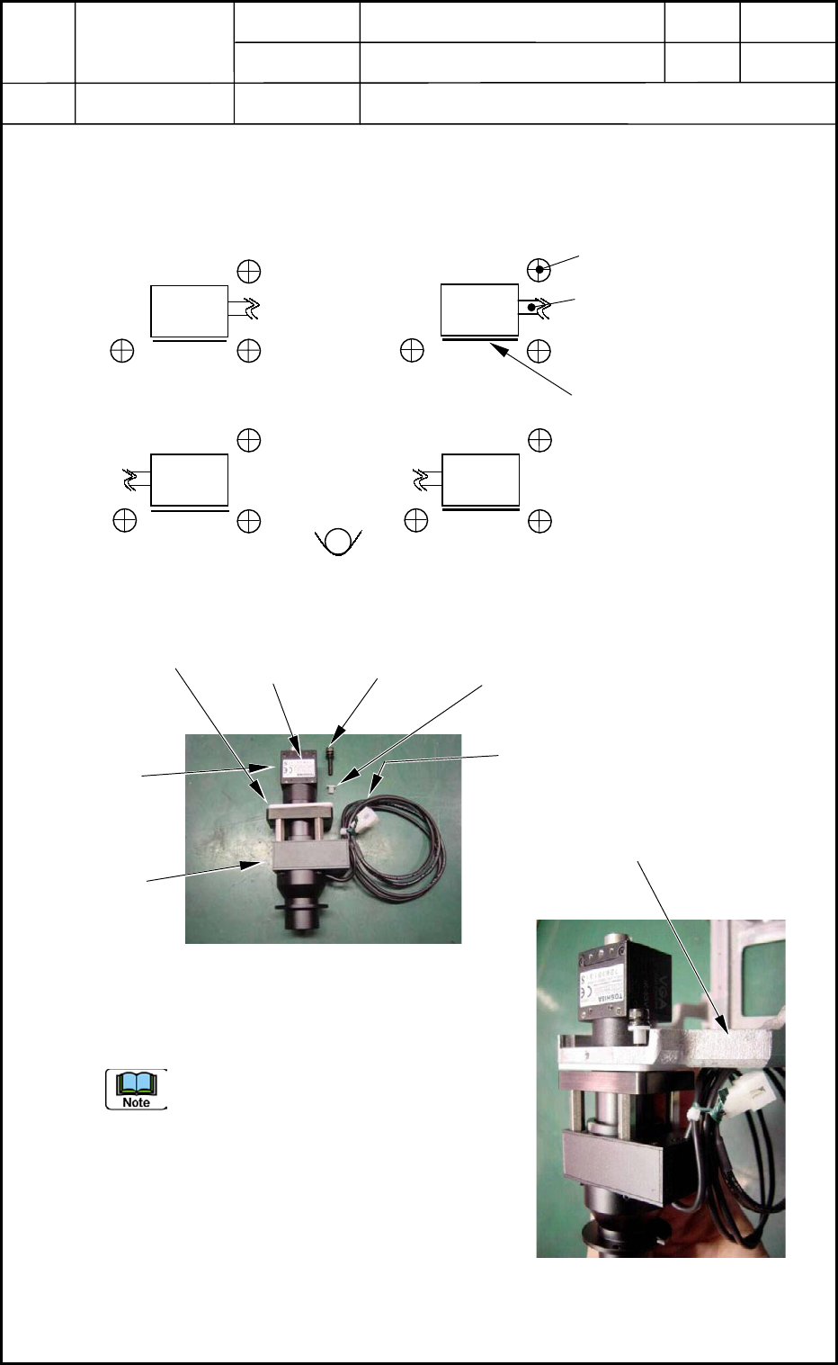
1.4 Directions of PEC Recognition Cameras
(Cameras and Lighting Units) for Attachment
Top View
Three setbolts are used to secure the camera.
Check the direction of the lighting cable
running from the camera and the direction
of the label.
0406-001
11-3
Setbolt for Camera Attachment
M4 L15 3 places
Lighting Cable
1
3
2 4
Label
Fig. K6 Directions of PEC Recognition Cameras
Camera
Camera
Camera
Camera
Label
M4 L15
SW,FW
Collar
Lighting Cable
Fig. K7 Composition of
PEC Recognition Camera
Camera
Section
Lighting
Section
Collar
Fig. K8 Attachment of
PEC Recognition Camera
Outer Frame