SM-131-006.pdf - 第112页
Device Name Chip Mounter Block Name Page No. Unit Name Revision Model Item GXH -1 Chapter 5 Head Section 4. Replacement of Nozzl e Shaft Nozzle Shaft 4.1 Detachment and Attachment of Nozzle Shaft (Single Unit) 4.1.1 Deta…
Device
Name
Chip Mounter
Block Name
Page No.
Unit Name
Revision
Model Item GXH-1
Chapter 5 Head Section
3. Replacement of Doughnut Board
UB22
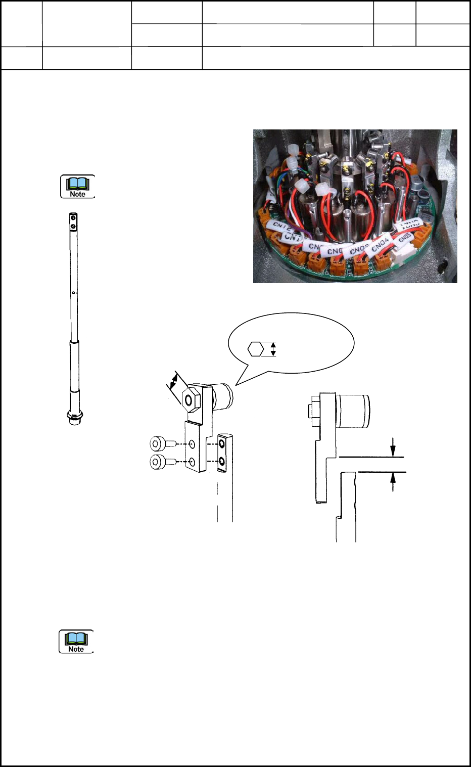
3.2 Attachment of Doughnut Board
(1) Put the doughnut boards (in the disconnected condition shown in Fig. E13) on the
DD motor and connect the connectors.
(2) Fix the board at the point where CN12 of the board is located just before the #1
nozzle and the dip switches are located slightly on the left side of the #1 nozzle when
the #1 nozzle is facing the front as shown in Fig. E11.
Apply "1401B" to the four M2 hexagonal supports for the fixation. (Fig. E14)
Confirm that no wires are trapped (pinched) and there is no interference between the
board and the frame when the motor section is rotated by hand.
(3) Connect Connectors CN1 through CN12 (Change-Over Valves), CN13, CN21, and
CN22 to the board as shown in Fig. E11.
Set the #1 and #5 dip switches to "ON".
(4) Attach the cover. (Fig. E14)
Apply "1401B" to the four bolts (M2L6).
M2 Support
M2 for Cover
Fig. E14 Doughnut Board Mounting Section
0406-001
5-10
Device
Name
Chip Mounter
Block Name
Page No.
Unit Name
Revision
Model Item GXH-1
Chapter 5 Head Section
4. Replacement of Nozzle Shaft
Nozzle Shaft
4.1 Detachment and Attachment of Nozzle Shaft (Single Unit)
4.1.1 Detachment of Nozzle Shaft (Single Unit)
When the two bolts (M1.6L3) are removed
as shown in Fig. E16, the nozzle shaft can
be disassembled from the cam follower.
Be sure not to drop the nozzle
shaft.
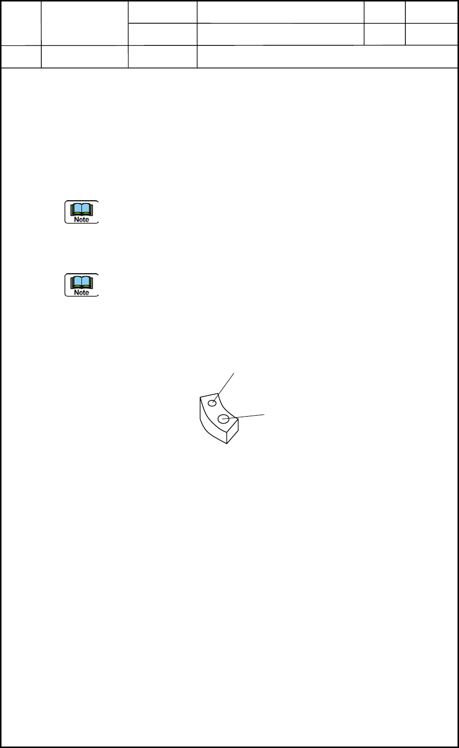
4.1.2 Attachment of Nozzle Shaft (Single Unit)
Assemble the cam follower section and the nozzle shaft with two bolts (M1.6L3).
• Tightening Torque: 720 gf/cm Screw Lock: 1401B
(a) The nozzle shaft and cam follower must be attached vertically as shown in Fig.
E18 without leaving any clearance between Face A of the cam follower and Face
B of the nozzle shaft.
(b) The nozzle shaft and the guide are regarded as an assembly (managed using the
same No.). Therefore, only the shaft or the guide cannot be replaced with a new
one.
4.1.3 Tightening Torque for Attachment of Cam Follower (Fig. E16)
• Use "LOCTITE" with tightening torque of 9.1 Ncm (900 gf/cm).
Fig. E15 Nozzle Shaft Unit Section
A
B
Fig. E18 Cam Follower Section
Mounting Face
M1.6L3
4 mm
Wrench Size
0.89 mm
Fig. E16 Cam Follower Mounting Section
Fig. E17 Nozzle Shaft
0406-001
5-11
Device
Name
Chip Mounter
Block Name
Page No.
Unit Name
Revision
Model Item GXH-1
Chapter 5 Head Section
4. Replacement of Nozzle Shaft
Nozzle Shaft Assembly
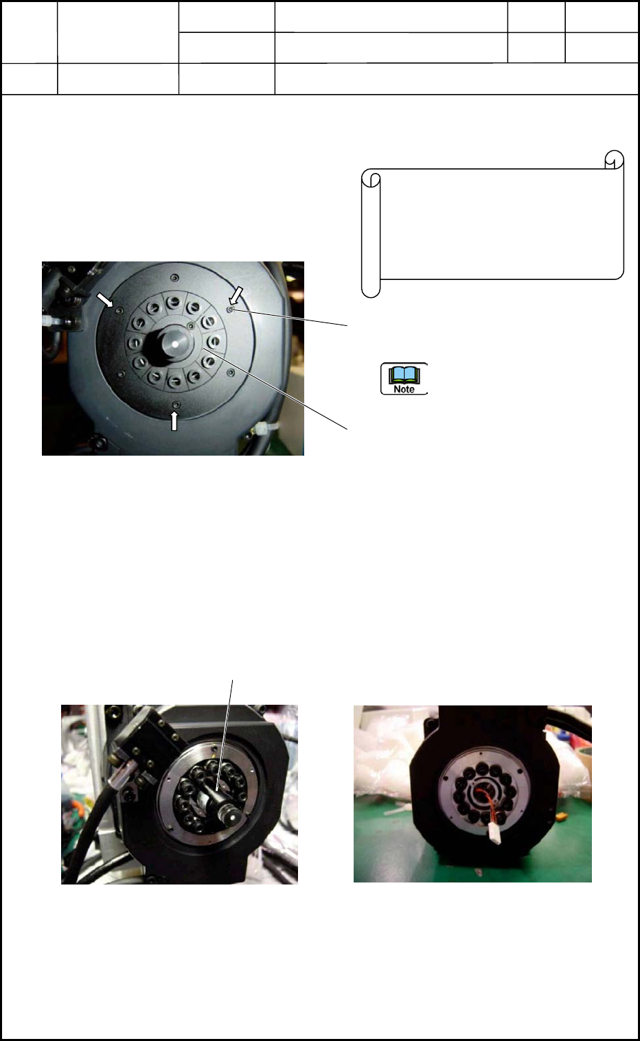
4.2 Detachment of Nozzle Shaft Assembly
4.2.1 Detachment of Large Diffusion Plate
(1) Remove the three screws (M1.6L5) of
the large diffusion plate (outer side).
Pay attention to the detachment
position. Pay attention to the
detachment position.
(2) Remove the two screws (M1.6L5) of the
small diffusion plate (inner side).
4.2.2 Detachment of Linear Measure Sensor (Fig. E20)
Remove the two screws (M1.6L5) of the linear measure sensor on the light emitting side
and detach the sensor from the motor side.
Do not detach the linear measure sensor on the light receiving side.
Disconnect the connector. (Fig. E21)
Springs are used at the lower area of the
nozzle shaft. Therefore, it is required to
attach a holding plate (drop prevention)
and detach the large diffusion plate in
the assembled condition.
Fi
g
. E19 Head Bottom Area
Linear Measure Sensor
on the Light Emitting Side
Fig. E20 Linear Measure Sensor Fig. E21 Linear Measure Sensor
Connector Section
0406-001
5-12