SM-131-006.pdf - 第241页
Device Name Chip Mounter Block Name Page No. Unit Name Revision Model Item GXH-1 Chapter 13 Layout of Electrical 9. Layout of Var iou s Bo ards Layout 9.1 Layout of Various Boards Identification of Boards: Symbol ID Symb…
Device
Name
Chip Mounter
Block Name
Page No.
Unit Name
Revision
Model ItemGXH-1
Chapter 13 Layout of Electrical
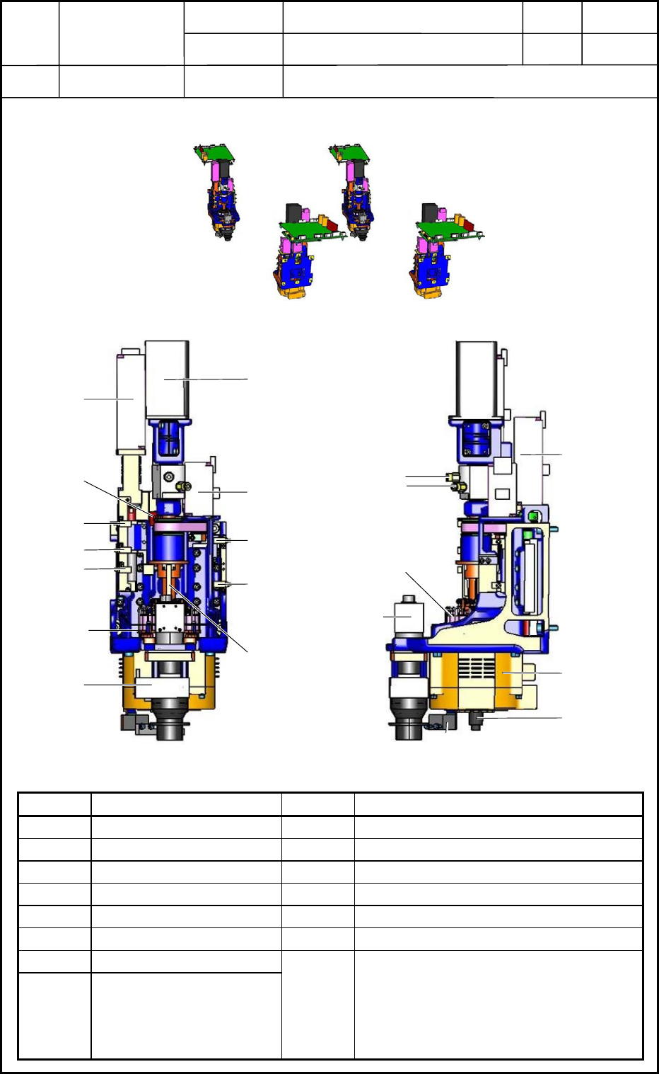
8. Layout of Head Section
Layout
8.1 Layout of Head Section
Symbol Name Symbol Name
U37 Slip Ring B3101 Nozzle Selection Position Detection Sensor
U04 Doughnut Board (UB22) B3102 Nozzle Up/Down Interlock Sensor
M31 Head Rotational Shaft B3103 Head Up/Down (-) Limit Sensor
M32 Nozzle Selection Shaft B3104 Nozzle Up/Down (+) Limit Sensor
M33 Nozzle Up/Down Shaft B3105 Nozzle Up/Down (-) Limit Sensor
M34 Head Up/Down Shaft B3106 Head Up/Down (+) Limit Sensor
E39 PEC Recognition Lighting
B0413T
B0413
Linear Measure Sensor
(Light Emission)
Linear Measure Sensor
(Light Reception)
Y0401
to
Y0412
Vacuum Switching Valves (12 pcs.)
0406-001
13-23
Rear Side
Front Side
Section A
Section B
Section C
Section D
Fig. M62 Whole View of Heads
Fig. M63 Magnified View of Head
M33
U37
M32
B3103
B3106
Nozzle
Up/Down Lever
E39
B3104
B3102
B3105
B3101
U04
PEC Recognition
Camera
Vacuum
Air Blow
Y0401 ~ Y0412
M34
M31
B0413T
B0413
Device
Name
Chip Mounter
Block Name
Page No.
Unit Name
Revision
Model ItemGXH-1
Chapter 13 Layout of Electrical
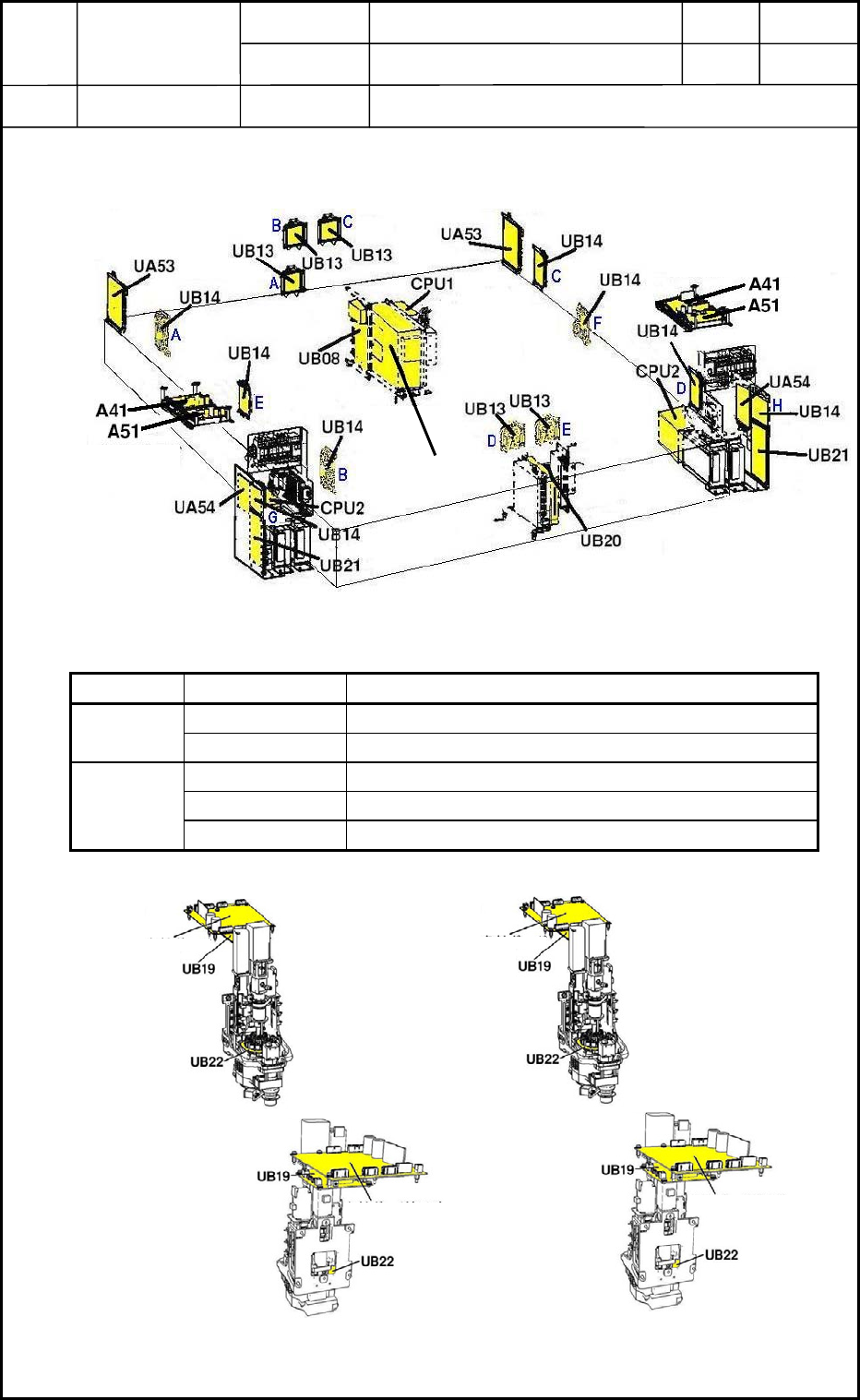
9. Layout of Various Boards
Layout
9.1 Layout of Various Boards
Identification of Boards:
Symbol ID Symbols Board Name
A Board for Light Tower
UB13
B,C,D,E Board for Operation Panel
A,B,C,D Board for Cutter Positioning
E,F Board for TransferUB14
G,H Board for Power Supply Section
Front Side of Machine
Rear Side of Machine
Multiaxis Board
Multiaxis Board
Recognition Box
Fig. M64 Arrangement of Various Boards
Front Side of Machine
Rear Side of Machine
Head B
Head A
Head C
Head D
Fig. M65 Arrangement of Boards for Heads
Multiaxis Board
(A31)
Multiaxis Board
(A31)
Multiaxis Board
(A31)
Multiaxis Board
(A31)
0406-001
13-24
Device
Name
Chip Mounter
Block Name
Page No.
Unit Name
Revision
Model ItemGXH-1
Chapter 13 Layout of Electrical
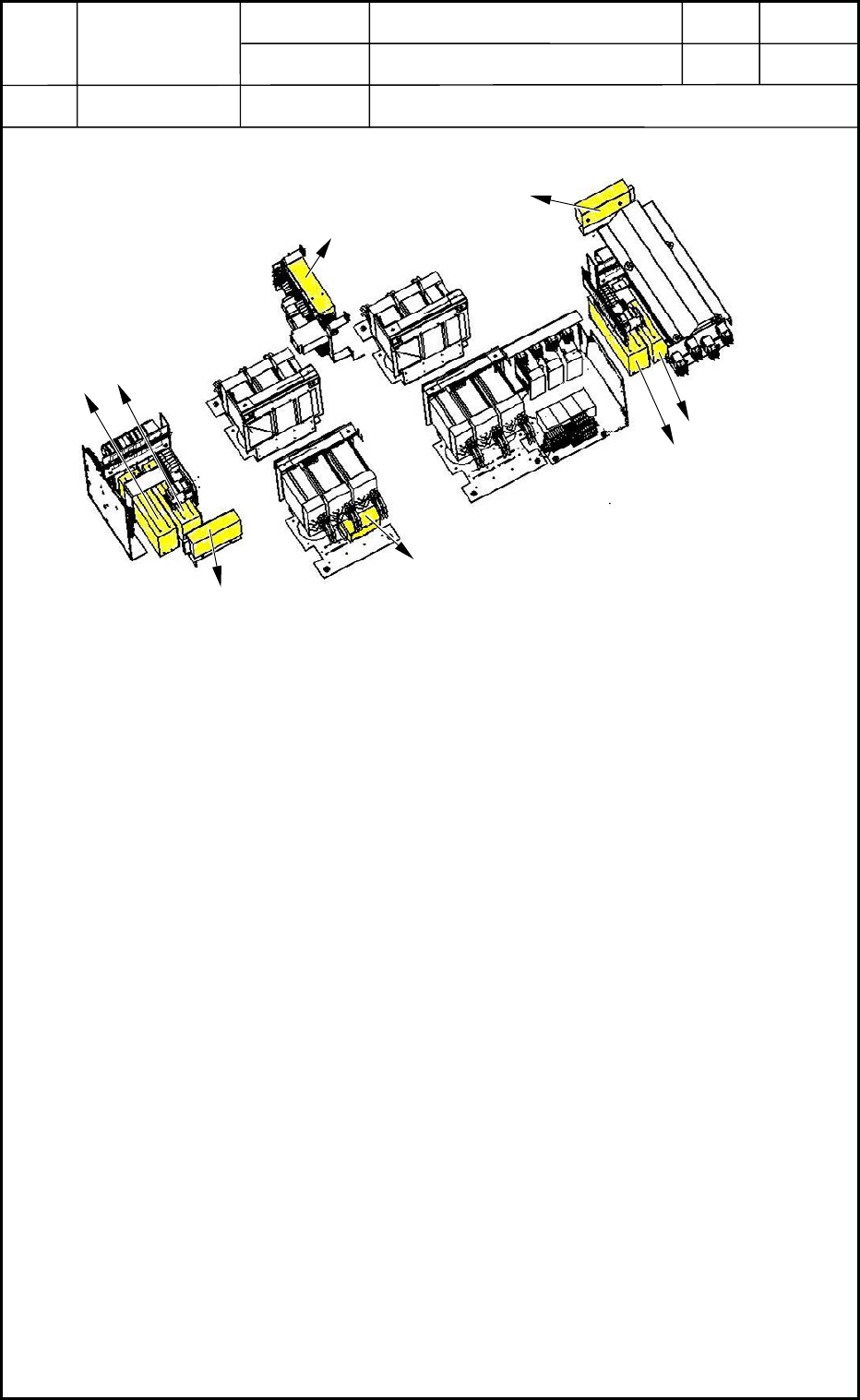
10. Layout of Each DC Power Units
Layout
10.1 Layout of DC Power Units
A: G01 (24 V DC)
1. 24A (For Safety Circuit)
2. 24B1 (For "INPUT")
3. 24B2 (For "OUTPUT", 24 V DC Loads, and 24 V DC Machine)
4. 24C (For Power Supply to Externals via I/F of Input/Output Machines)
5. 24F (For Control Power Supply of Head Multiaxis Servomotor Drivers)
B: G03 (48 V DC)
1. 48E2A (For Transfer NL-L, NA-L1, and NB-L1)
2. 48E3A (For Chute Width NL-W1, NL-W2, NB-W1, and NB-W2)
3. 48E4A (For Transfer NR-L and NC-L1)
4. 48E5A (For Chute Width NR-W1 and NR-W2)
C: G05 (5 V DC)
1. 5E (For Control Power Supply to Transfer Multiaxis SMD on R Side and Main Power
Supply)
D: G05 (5 V DC)
1. 5E (For Control Power Supply to Transfer Multiaxis SMD on L Side and Main Power
Supply)
E: G04 (24 V DC)
1. 24G (For Feeders C and D)
F: G02 (48 V DC)
1. 48D3A (For Main Power Supply to Head C Multiaxis SMD)
2. 48D3B (For Main Power Supply to Head D Multiaxis SMD)
G: G04 (24 V DC)
1. 24G (For Feeders A and B)
H: G02 (48 V DC)
1. 48D3C (For Main Power Supply to Head A Multiaxis SMD)
2. 48D3D (For Main Power Supply to Head B Multiaxis SMD)
0406-001
13-25
A
B
C
D
E
F
G
H
Front Side of Machine
Rear Side of Machine
Fig. M66 Arrangement of DC Power Units