SM-131-006.pdf - 第204页
Device Name Chip Mounter Block Name Page No. Unit Name Revision Model Item GXH-1 Chapter 11 Recognition Section 1. Replacement of PEC Recognition Camera 1.4 Directions of PEC Recognition Cameras (Cameras and Lighting Uni…
Device
Name
Chip Mounter
Block Name
Page No.
Unit Name
Revision
Model ItemGXH-1
Chapter 11 Recognition Section
1. Replacement of PEC Recognition Camera
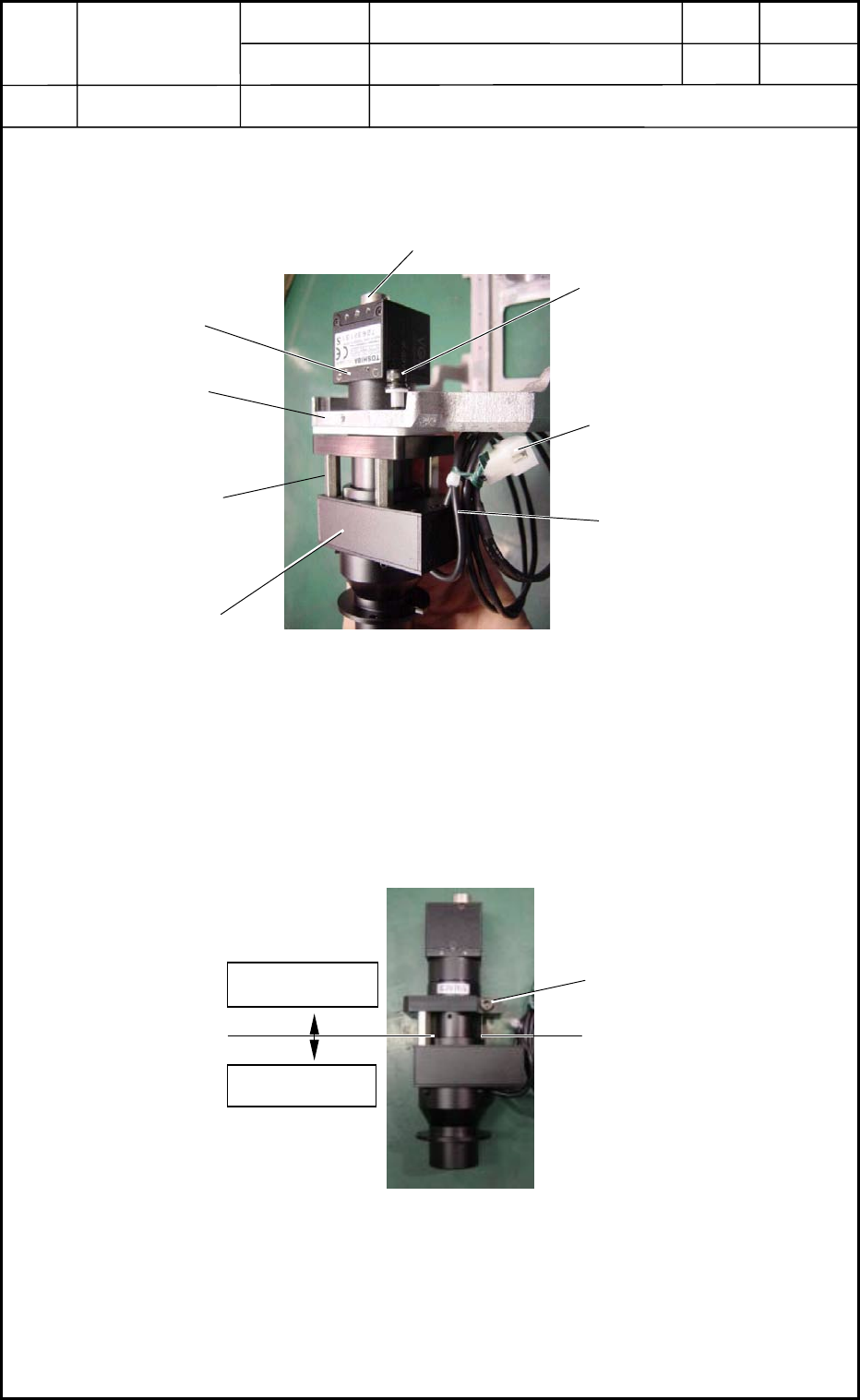
(5) Remove the three bolts (M4L16) and detach the camera unit from the outer frame.
(Fig. K4)
1.3 Detachment of PEC Recognition Camera
(1) Remove the bolt.
(2) Detach the three supports in Fig. K4.
(3) Detach the camera and lighting sections.
Lighting Section
6-Pin
Nylon Connector
M4 L16
Lighting Cable
Fig
Camera Section
Fig. K4 PEC Recognition Camera Unit Section
Outer Frame
Support
Camera Cable Connecting Area
Fig. K5 PEC Recognition Camera and Lighting Sections
Camera Section
Lighting Section
Bolt
0406-001
11-2
Device
Name
Chip Mounter
Block Name
Page No.
Unit Name
Revision
Model ItemGXH-1
Chapter 11 Recognition Section
1. Replacement of PEC Recognition Camera
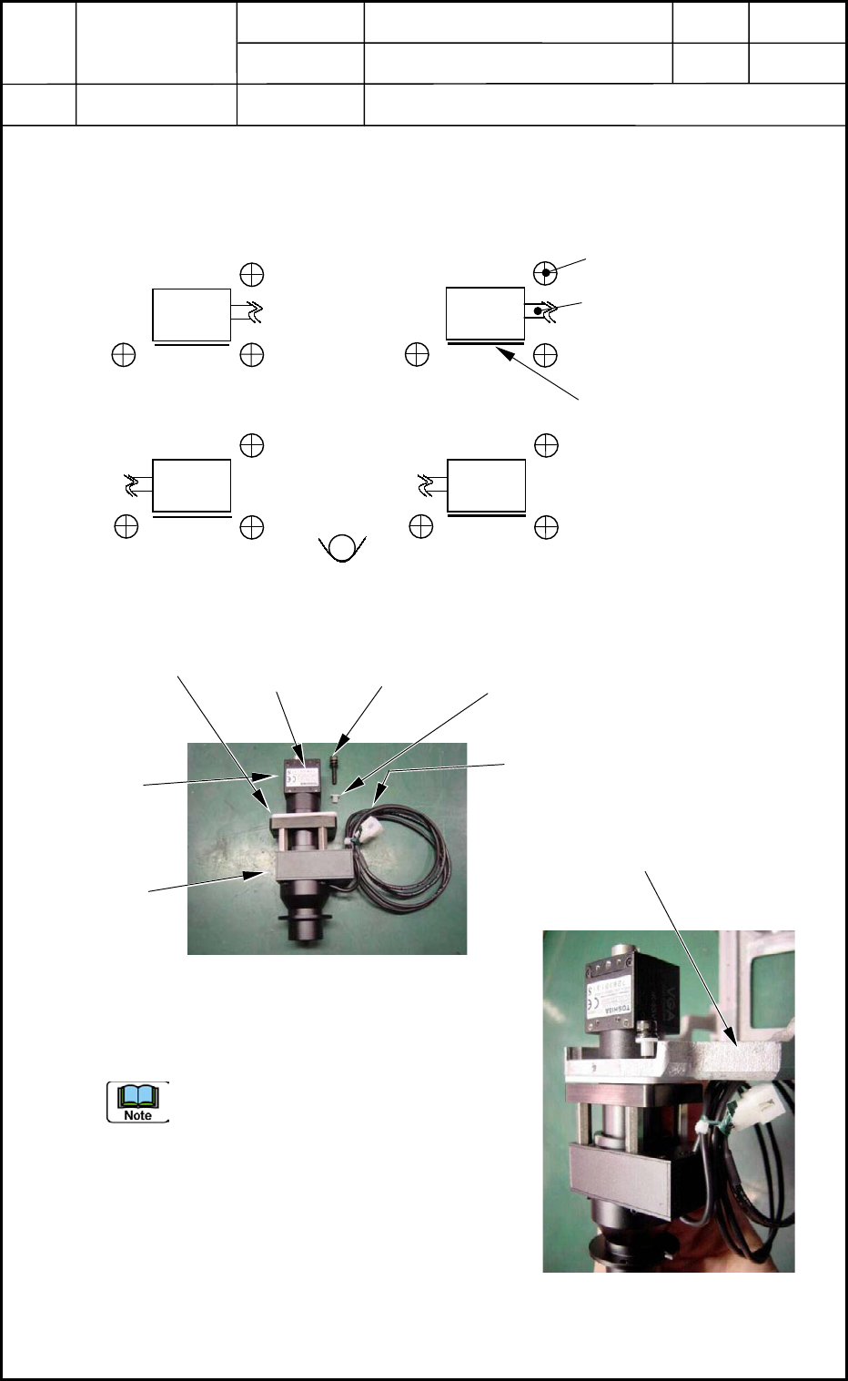
1.4 Directions of PEC Recognition Cameras
(Cameras and Lighting Units) for Attachment
Top View
Three setbolts are used to secure the camera.
Check the direction of the lighting cable
running from the camera and the direction
of the label.
0406-001
11-3
Setbolt for Camera Attachment
M4 L15 3 places
Lighting Cable
1
3
2 4
Label
Fig. K6 Directions of PEC Recognition Cameras
Camera
Camera
Camera
Camera
Label
M4 L15
SW,FW
Collar
Lighting Cable
Fig. K7 Composition of
PEC Recognition Camera
Camera
Section
Lighting
Section
Collar
Fig. K8 Attachment of
PEC Recognition Camera
Outer Frame
Device
Name
Chip Mounter
Block Name
Page No.
Unit Name
Revision
Model ItemGXH-1
Chapter 11 Recognition Section
1. Replacement of PEC Recognition Camera
1.5 Attachment of PEC Recognition Camera
Attach the camera unit and the outer frame with three bolts (M4L15).
Dimensions : X = 6.33 mm, 5.67 mm Y = 4.5 mm
(Groove of Outer Frame and Camera) (Edge of Outer Frame and Camera)
Two types of jigs must be used depending on which heads Cameras #1 and #3 or #2 and #4
should be installed.
Top View
1 3
2
4
Fig. K9 Jig Size and Arrangement
Camera
Camera
Camera
Camera
4.5
4.5
4.5
4.5
5.67
5.67
6.33
6.33
Unit: mm
Fig. K10 Jig Arrangement
for Cameras #2 and #4
4.5
5.67
Fig. K11 Jig Arrangement
for Cameras #1 and #3
6.33
Unit: mm
Unit: mm
0406-001
11-4