SM-131-006.pdf - 第173页
0406-001 8- B

Chapter 8
Component Supply Section
This chapter describes how to assemble, replace, and set
up the component supply section.
• Assembly of Feeder Positioning Section
• Replacement of Cylinder and Valve for Feeder Clamping
• Replacement of Feeder Connector
• Replacement of Batch Connector Cable
• Setting of Lifted Feeder Detection Sensor
0406-001 8-A

0406-001 8-B
Device
Name
Chip Mounter
Block Name
Page No.
Unit Name
Revision
Model Item GXH-1
Chapter 8 Component Supply Section
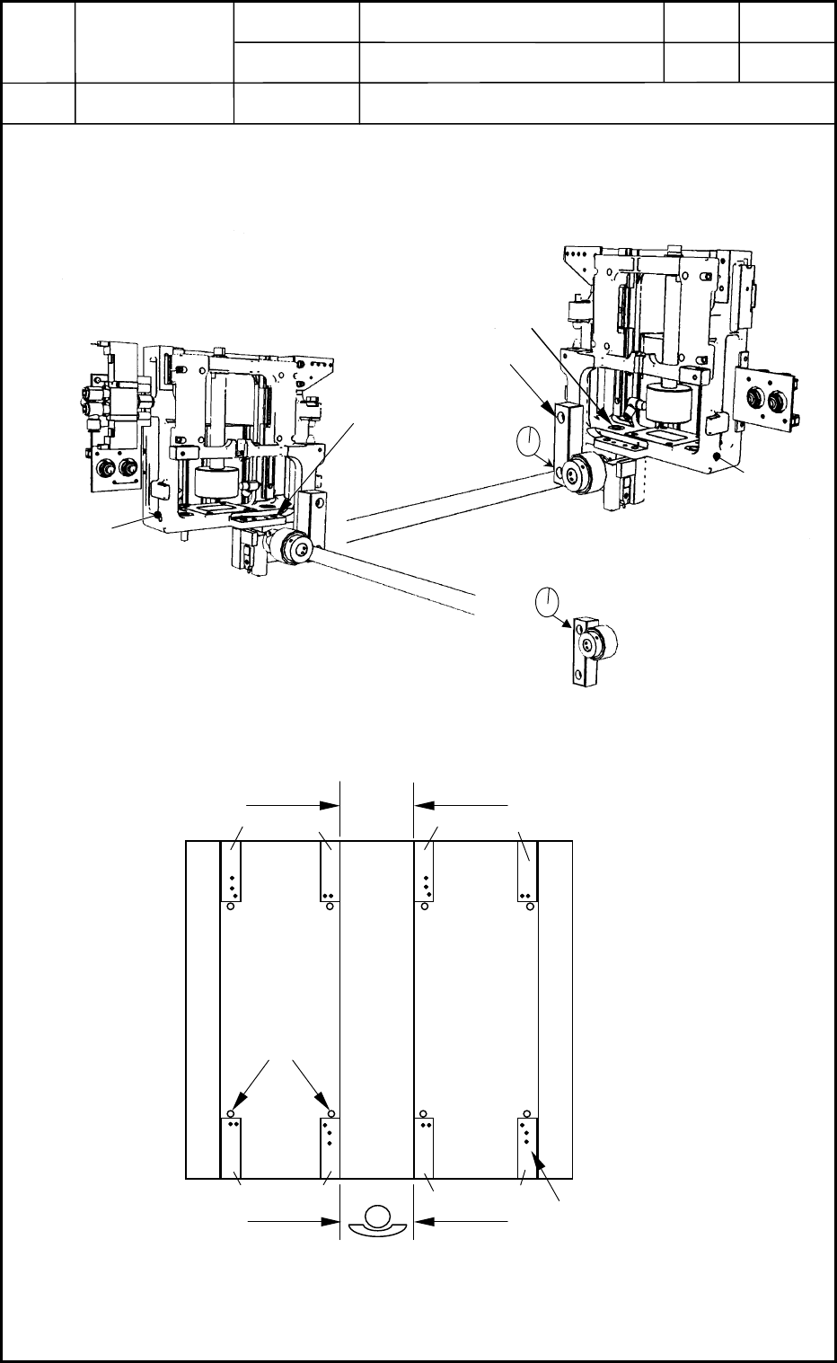
1. Assembly of Feeder Positioning Section
1.1 Unit Attachment
(1) Attach Section A (Fig. H1) and Section B (Fig. H2) to the main body.
0406-001
8-1
M
8
L2
0
Fig. H2 Positioning of Left Section
Section B (Left)
Fig. H1 Positioning of Right Section
(Ascending Position)
Section A (Right)
M10L40
M8L30
Fig. H3 Positioning of Right Section
(Descending Position)
Unit Base
Alignment
Center Stand
Positioning
Pins
Alignment
Alignment
Frame
B A B A
A B
Alignment
A B
Fig. H4 Unit Mounting Position