SM-131-006.pdf - 第98页
Device Name Chip Mounter Block Name Page No. Unit Name Revision Model Item GXH-1 Chapter 4 Beam Section 6. Replace of Linear Scale 6.2.3 Attachment of Y-Axis Linear Scale Holder (1) Attach Block A and fix it as shown in …
Device
Name
Chip Mounter
Block Name
Page No.
Unit Name
Revision
Model ItemGXH-1
Chapter 4 Beam Section
6. Replace of Linear Scale
6.2 Replacement of Y-Axis Linear Scale
6.2.1 Detachment of Y-Axis Linear Scale
(1) Set the power breaker of the machine
to "OFF".
(2) Detach the covers, etc., of the machine
to prepare for the work.
(3) Detach the linear scale fixing block
and pull out the linear scale as shown
in Fig. D27.
6.2.2 Attachment of Y-Axis Linear Scale
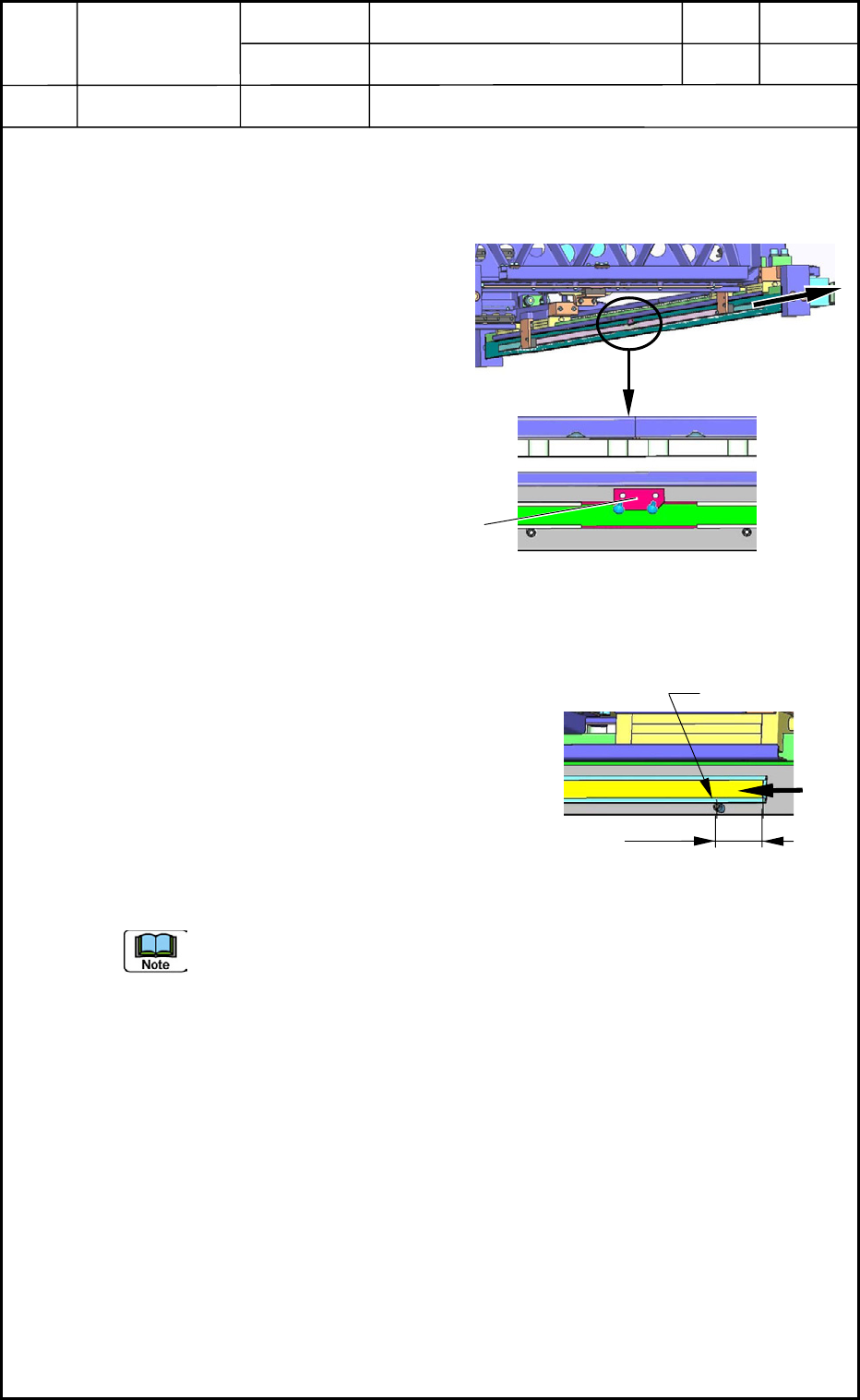
(1) Slowly insert the linear scale into the
holder as shown in Fig. D28. Be careful not
to make nicks on the linear scale.
(2) Position the linear scale.
Distance between Positioning Pin and
Linear Scale End: 26.5 mm
(3) Fix the linear scale with the fixing block as
shown in Fig. D28.
When the teaching operation in (6) is performed and the Y2-axis linear scale is
attached after (1) through (3), the replacement work is completed.
As for the Y1 axis, proceed to the following steps.
(4) Turn on the power supply to the machine and zero the beam.
(5) Move the Y1 axis by 50 mm in the outward direction through the manual axis
operation and re-adjust the scale position of the Y1 axis so that the emitted light
cannot be received by the limit sensor at the adjusted position.
(6) Adjust the offsets. Now the attachment of the scale is completed.
Refer to "6. Adjustment of Offsets" in Chapter 5 for details.
Pullout
Fig. D27 Y-Axis Linear Scale
Magnified View
Linear Scale
Fixin
g
Block
Fig. D28 Positioning of Linear Scale
Positioning Pin
26.5 mm
0406-001
4-12
Device
Name
Chip Mounter
Block Name
Page No.
Unit Name
Revision
Model ItemGXH-1
Chapter 4 Beam Section
6. Replace of Linear Scale
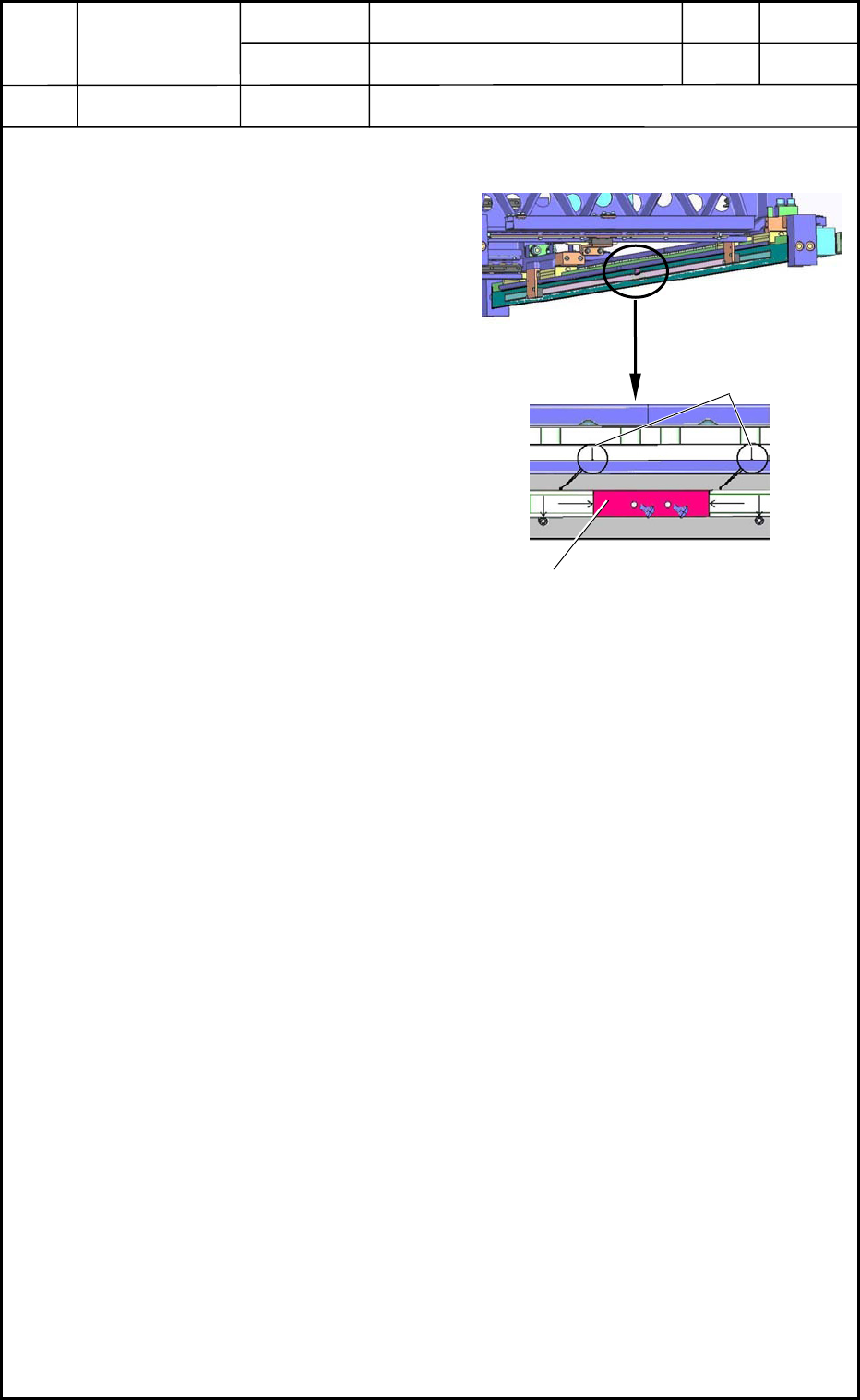
6.2.3 Attachment of Y-Axis Linear Scale Holder
(1) Attach Block A and fix it as shown in
Fig. D29.
(2) Put a double-faced tape on the back
sides of both linear scale holders.
Make the back sides get in touch with
the positioning pins and Block A of
the linear scale holder and push the
back sides lightly against the plate.
(3) Make the dial gauge run all the way
along the side face of the linear scale
holder and adjust the difference in the
horizontal direction of the linear scale
holder for 0.1 mm or less. After that,
push the linear scale holder strong
enough to be secured.
Y-Axis Linear Scale
Magnified View
Dial Gauge
Fig. D29
Block A
0406-001
4-13
Device
Name
Chip Mounter
Block Name
Page No.
Unit Name
Revision
Model ItemGXH-1
Chapter 4 Beam Section
0406-001
4-14