SM-131-006.pdf - 第115页
Device Name Chip Mounter Block Name Page No. Unit Name Revision Model Item GXH -1 Chapter 5 Head Section 4. Replacement of Nozzl e Shaft Nozzle Shaft Assembly 4.2.4 Dis assembly of Cam Foll ower Secti on Disassem ble the…
Device
Name
Chip Mounter
Block Name
Page No.
Unit Name
Revision
Model Item GXH-1
Chapter 5 Head Section
4. Replacement of Nozzle Shaft
Nozzle Shaft Assembly
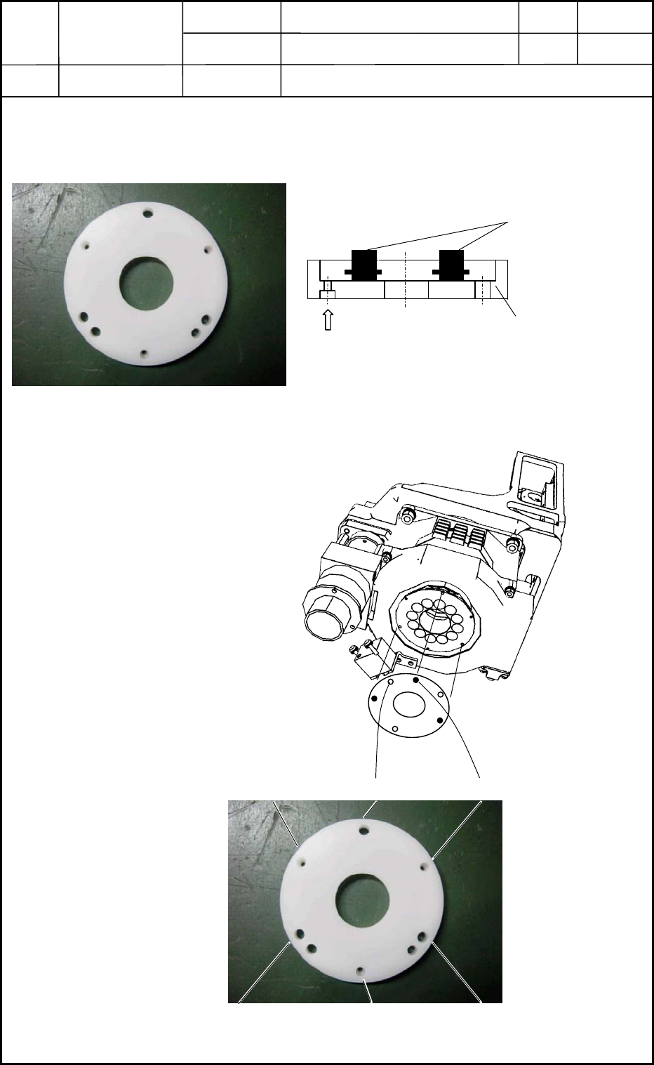
4.2.3 Attachment of Nozzle Shaft Holding Jig
Attach the nozzle shaft holding jig to the area where the large diffusion plate was detached.
(Figs. E22 and E23)
(1) Attach the nozzle shaft holding
jig securely to the nozzle shaft
assembly (the position of the
large diffusion plate) with three
screws (M1.6L5).
(2) Connect the nozzle shaft
assembly with the motor
section.
Assemble the jig so that the
three screws (M1.6L5) can stay
visible.
0406-001
5-13
Nozzle Shaft Holding Jig
Nozzle Shaft
Fig. E23 Jig Usage
M1.6L5 (3 places)
Fig. E22 Nozzle Shaft Holding Jig
Fig. E24 Attachment of
Nozzle Shaft
Holding Jig
Fig. E25 Nozzle Shaft Holding Jig (Hole Position)
B
B
B
A
AA
Device
Name
Chip Mounter
Block Name
Page No.
Unit Name
Revision
Model Item GXH-1
Chapter 5 Head Section
4. Replacement of Nozzle Shaft
Nozzle Shaft Assembly
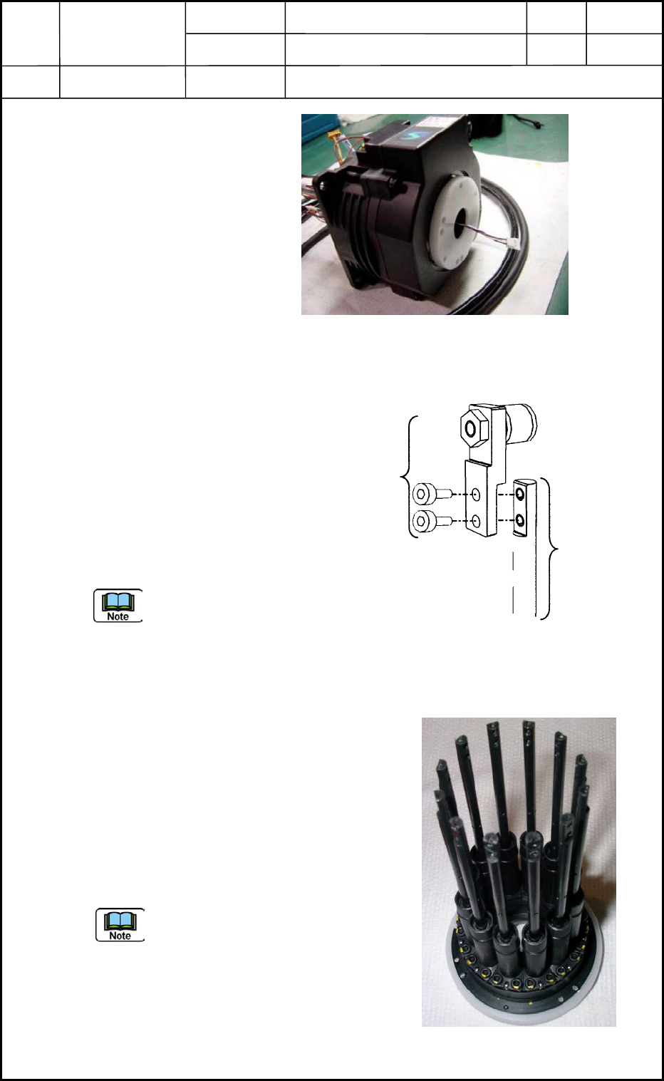
4.2.4 Disassembly of Cam Follower Section
Disassemble the cam follower
section (located at the upper area
of the nozzle shaft) from the
nozzle shaft as shown in Fig. E27.
Remove the two bolts (M1.6L3).
Follow the same procedure to
disassemble the cam followers for
the twelve nozzle shafts.
The disassembled cam
follower should be
kept so as to match the
nozzle No.
4.2.5 Detachment of Nozzle Shaft Assembly
(1) Remove the three screws (M1.6L5)
(marked "B" in Figs. E24 and E25).
(2) Pull down the nozzle shaft holding jig.
When the jig is kept too tight, try to
push several areas on the upper part of
the nozzle shaft by hand.
(3) Take out the nozzle shaft assembly,
keeping it in the condition shown in Fig.
E28.
Be sure not to drop the assembly.
Fig. E26 Assembled Nozzle Shaft Holding Jig
Fig. E28 Nozzle Shaft Assembly + Jig
0406-001
5-14
Fig. E27 Disassembly of Cam Follower Section
from Nozzle Shaft
M1.6L3
Cam Follower
Section
Nozzle Shaft
Device
Name
Chip Mounter
Block Name
Page No.
Unit Name
Revision
Model Item GXH-1
Chapter 5 Head Section
4. Replacement of Nozzle Shaft
Nozzle Shaft Assembly
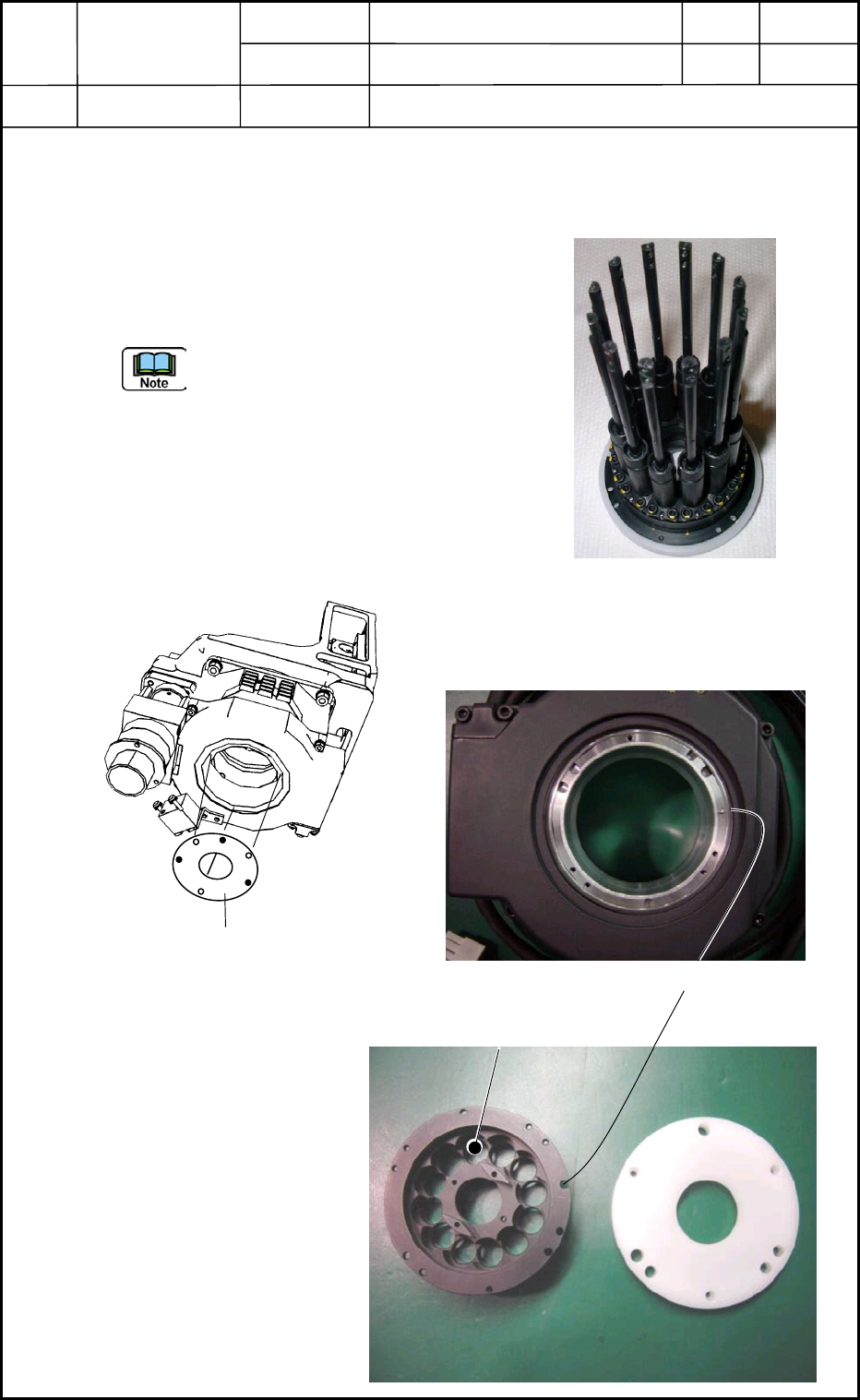
4.3 Attachment of Nozzle Shaft Assembly
4.3.1 Attachment of Assembly to DD Motor Side
(1) Attach the nozzle shaft assembly (Fig. E29) to
the DD motor side with three screws
(M1.6L5). (Fig. E30)
(a) Align the cutout of the positioning
pin (located at the bottom of the
DD motor) with the cutout of the
nozzle shaft assembly side (Figs.
E31 and E32) and insert the
assembly into the DD motor side.
(b) Do not leave any clearance at the
mating portion.
Fig. E29 Nozzle Shaft Assembly
Fig. E30 Attachment of Nozzle Shaft Assembly
Nozzle Shaft Assembly
Positioning Pin
Position of #1 Nozzle
Fig. E31 Bottom of DD Moto
r
Fig. E32 Nozzle Shaft Attachment Section
and Nozzle Holding Jig
0406-001
5-15