SM-131-006.pdf - 第82页
Device Name Chip Mounter Block Name Page No. Unit Name Revision Model Item GXH-1 Chapter 3 Various Setting 2. Setting of Various Boards 2.11 Setting of HLS Center Board • The HLS center board is used in the CPU2 box. Ref…

Device
Name
Chip Mounter
Block Name
Page No.
Unit Name
Revision
Model ItemGXH-1
Chapter 3 Various Setting
2. Setting of Various Boards
2.9 Setting of Multiaxis Driver Boards
• Eight pieces of multiaxis driver boards are used in the head and transfer sections.
Refer to "8. Layout of Head Section", "1.5 Layout of BL Block", and "1.6 Layout of
BR Block" in Chapter 13 for the location.
2.9.1 Setting of Boards
When the multiaxis driver boards are
used in the transfer or the head section,
CS1 and SW1 must be set as shown in
Fig. C9.
2.10 Setting of Motion Control Boards
• The motion control boards are used in the CPU2 box.
Refer to "1.8 Layout of FB Block" in Chapter 13 for the location.
2.10.1 Setting of Dip Switches
Set Dip Switch SW1 of the U82, U83, and U84 boards as shown in Fig. C10.
Fig. C9 Setting of Switch for Multiaxis
Driver Board
Fig. C10 Dip Switches of Motion Control Boards
0406-001
3-6
Device
Name
Chip Mounter
Block Name
Page No.
Unit Name
Revision
Model ItemGXH-1
Chapter 3 Various Setting
2. Setting of Various Boards
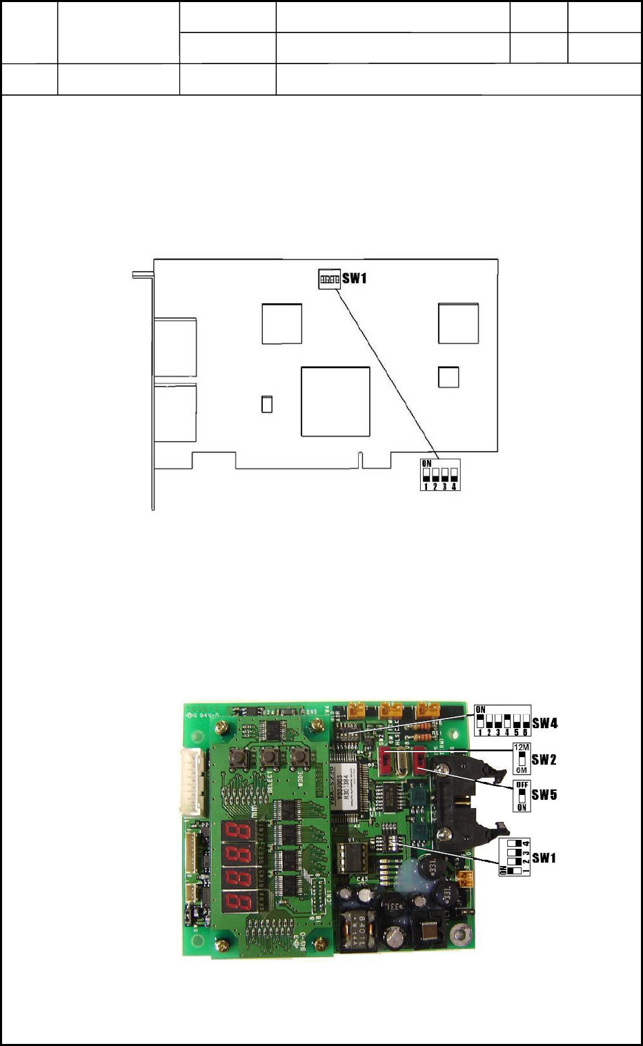
2.11 Setting of HLS Center Board
• The HLS center board is used in the CPU2 box.
Refer to "1.8 Layout of FB Block" in Chapter 13 for the location.
2.11.1 Setting of Dip Switch
Set Dip Switch SW1 as shown in Fig. C11.
2.12 Setting of Linear Measure Sensor Control Board
• The linear measure sensor control board is used in the head section.
Refer to "7. Layout of Beam Section" in Chapter 13 for the location.
2.12.1 Setting of Dip Switches
Set Dip Switches SW1, SW2, SW4, and SW5 as shown in Fig. C12.
Fig. C11 Dip Switch of HLS Center Board
Fig. C12 Dip Switches of Linear Measure Sensor
Control Board
0406-001
3-7
Device
Name
Chip Mounter
Block Name
Page No.
Unit Name
Various Adjustments
Revision
Model ItemGXH-1
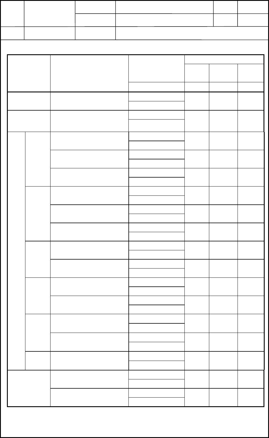
Specified Tensions of Various Belts Table C3
Setting of Tension Meter
Specified
Tensions
Width
Unit
Weight
Span
Unit Name Belt Name
Unit mm gf/cm mm
28 to 32 N
Head Section
Nozzle Selection Axis
Motor Belt
2.9 to 3.3 kgf
92.540
59 to 69 N
Backup Table
Section
Table Up/Down Axis
Timing Belt
6 to 7 kgf
12 0.25 250
15.8 to 20.8 N
Motor Belt for NL/NR
Transfer
1.6 to 2.1 kgf
90.1359
74 to 84 N
NL/NR Width
Adjusting Belt
7.5 to 8.5 kgf
15 0.25 77
4.3 to 5.3 N
NL
Section
Belt for NL/NR Transfer
0.44 to 0.54 kgf
2 0.13 165
15.8 to 20.8 N
Motor Belt for NL/NR
Transfer
1.6 to 2.1 kgf
90.1359
74 to 84 N
NL/NR Width
Adjusting Belt
7.5 to 8.5 kgf
15 0.25 77
4.3 to 5.3 N
NR
Section
Belt for NL/NR Transfer
0.44 to 0.54 kgf
2 0.13 165
15.8 to 20.8 N
Motor Belt for NA Transfer
1.6 to 2.1 kgf
90.1346
4.3 to 5.3 N
NA
Section
Belt for NA transfer
0.44 to 0.54 kgf
20.1367
15.8 to 20.8 N
Motor Belt for NB Transfer
1.6 to 2.1 kgf
90.1346
4.3 to 5.3 N
NB
Section
Belt for NB Transfer
0.44 to 0.54 kgf
20.1367
15.8 to 20.8 N
Motor Belt for NC Transfer
1.6 to 2.1 kgf
90.1346
4.3 to 5.3 N
NC
Section
Belt for NC Transfer
0.44 to 0.54 kgf
20.1367
44 to 54 N
Transfer Section
Width Chute Width Adjusting Belt
4.5 to 5.5 kgf
9 0.25 510
44 to 54 N
Cutter Transfer Belt
4.5 to 5.5 kgf
9 0.25 675
44 to 54 N
Cutter
Section
Cutter Motor Belt
4.5 to 5.5 kgf
9 0.25 87.8
0406-001
Chapter 3 Various Setting
3. Specified Tensions of Various Belts
3-8