SM-131-006.pdf - 第231页
Device Name Chip Mounter Block Name Page No. Unit Name Revision Model Item GXH-1 Chapter 13 Layout of Electrical 2. Layout of Cutter & Component Recognition Camera Layout 2.1 Layout of Cutter & Component Recognit…
Device
Name
Chip Mounter
Block Name
Page No.
Unit Name
Revision
Model ItemGXH-1
Chapter 13 Layout of Electrical
1. Layout of Underframe
Layout
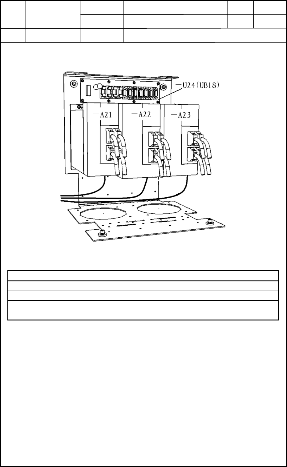
1.9 Layout of BF Blocks
Symbol Name
A21 X-Axis Servoamplifier
A22 Y1-Axis Servoamplifier
A23 Y2-Axis Servoamplifier
U24 Beam Relay Board UB18
0406-001
13-13
Fig. M36 Arrangement of Beam Amplifiers
Device
Name
Chip Mounter
Block Name
Page No.
Unit Name
Revision
Model ItemGXH-1
Chapter 13 Layout of Electrical
2. Layout of Cutter & Component Recognition Camera
Layout
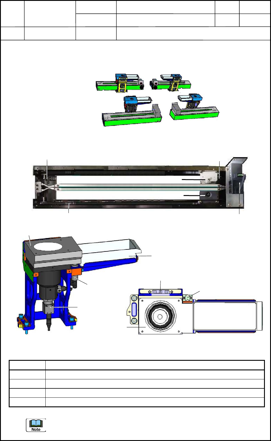
2.1 Layout of Cutter & Component Recognition Camera
Symbol Name
M63 Cutter Axis Motor
B6301 Cutter (+) Origin Sensor
B6302 Cutter (-) Origin Sensor
B61 Component Recognition Camera
The (+) origin sensor is located on the motor mounting side and the (-) origin sensor on the
cutter replacement position side.
0406-001
13-14
Rear Side
Front Side
Section A
Section B
Section C
Section D
Fig. M37 Cutter & Component Recognition Camera
M63
B6301
B6302
Upper Blade
Lower Blade
Belt
Fig. M38 Cutter Unit
Lighting Unit
B61
Lighting Fiber
Component Storage Box
Lighting Unit
Glass Jig Base
Mark for Teaching
(From the front left side)
(Top View)
Component
Storage Box
Fig. M39 Component Recognition Camera
Device
Name
Chip Mounter
Block Name
Page No.
Unit Name
Revision
Model ItemGXH-1
Chapter 13 Layout of Electrical
3. Layout of Nozzle Stocker Section
Layout
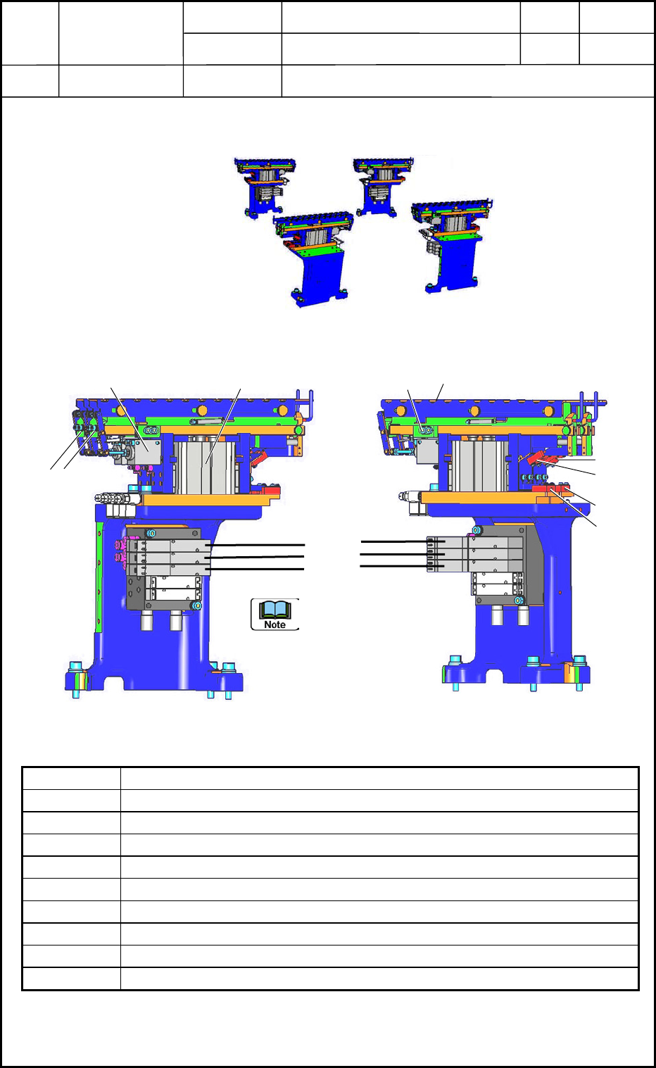
3.1 Layout of Nozzle Stocker Section
Symbol Name
B0918 Nozzle Stocker Unit Lower Limit Detection Sensor 1
B0919 Nozzle Stocker Unit Lower Limit Detection Sensor 2
B0920 Nozzle Stocker Shutter Closing Check Sensor 1
B0921 Nozzle Stocker Shutter Closing Check Sensor 2
B0922 Nozzle Stocker Clamping Check Sensor 1
B0923 Nozzle Stocker Clamping Check Sensor 2
Y0935 Nozzle Stocker Shutter Opening Valve
Y0936 Nozzle Stocker Ascending 1
Y0937 Nozzle Stocker Ascending 2
Section A
Section B
Section D
Rear Side
Front Side
Fi
g
. M40 Whole View of Nozzle Stockers
Section C
B0922
B0918
Y0937
Y0936
Y0935
B0923
B0919
B0921
(
B0920
)
Shutter
Open/Close Cylinder
Stocker
Up/Down Cylinder
(From the front left side)
(From the front right side)
2
1
Order of Nozzle
Stockers: Nos. 1 and 2 of
Devices
Fig. M41 Nozzle Stocker
0406-001
13-15