SM-131-006.pdf - 第314页
Device Name Chip Mounter Block Name Page No. Unit Name Revision Model Item GXH -1 Chapter 18 Pack aging 2. Packag ing Procedure (1) Remove the anchor bolt located on the front side of the m achine. Lock the head of the a…
Device
Name
Chip Mounter
Block Name
Page No.
Unit Name
Revision
Model Item GXH-1
Chapter 18 Packaging
2. Packaging Procedure
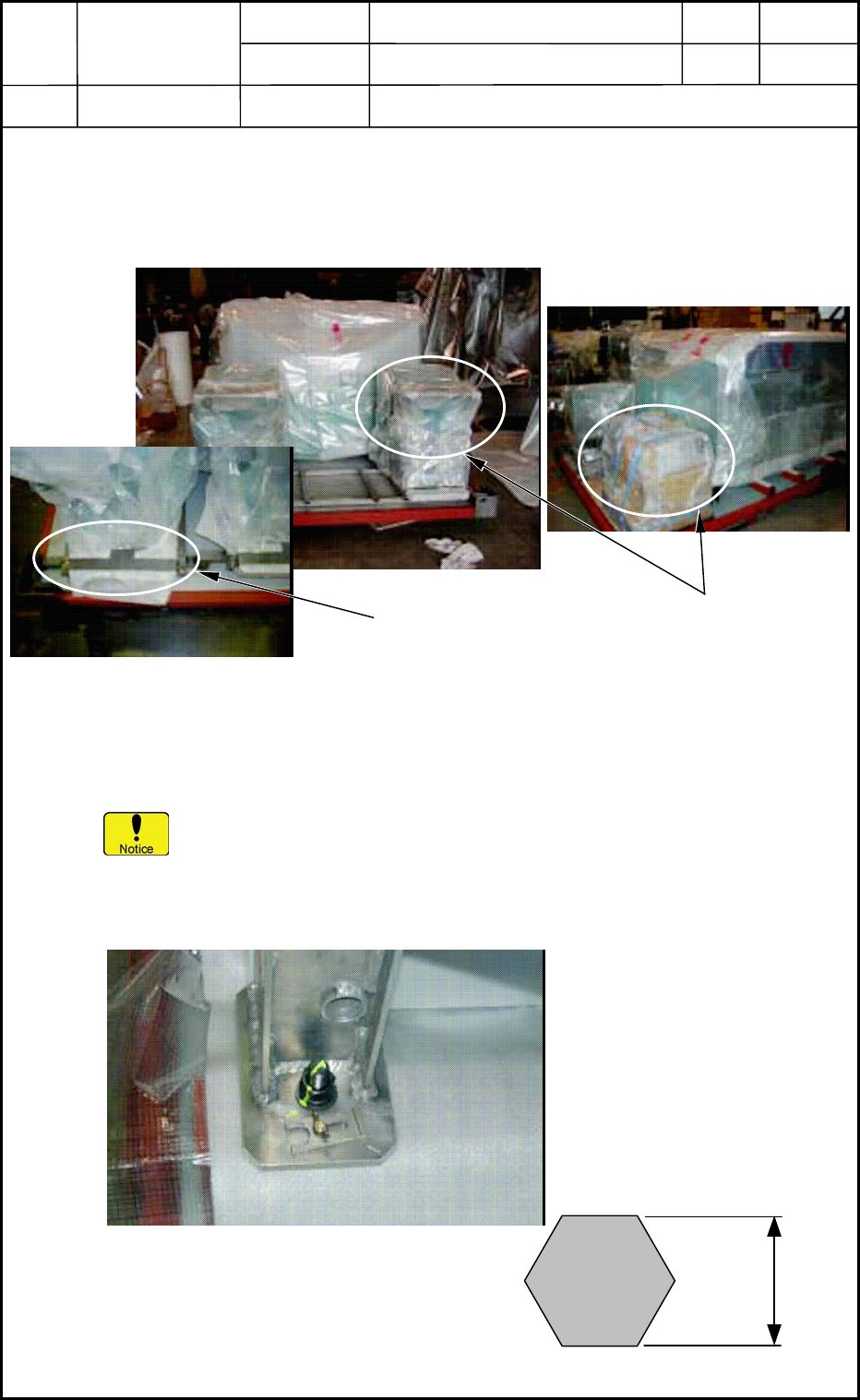
2.2.4 Detachment of Accessory Parts Boxes
The accessory parts are put in the fixed boxes located on the spaces near both end panels.
Remove the metal fixtures and take out the boxes.
Fig. R12
2.2.5 Detachment of Main Body
• Remove the damp-barrier material that is used to protect the main body of the
machine.
If you use a cutter, etc., make sure not to nick the surface of the main body inside
the material.
• The main body is fastened to the skid base with four anchor bolts (M20). Remove
these anchor bolts.
Fig. R13
Metal Fixtures for
Accessory Parts Boxes
Accessory Parts Boxes
30 mm
Anchor Bolt M20
18-14
0512-001
Device
Name
Chip Mounter
Block Name
Page No.
Unit Name
Revision
Model Item GXH-1
Chapter 18 Packaging
2. Packaging Procedure
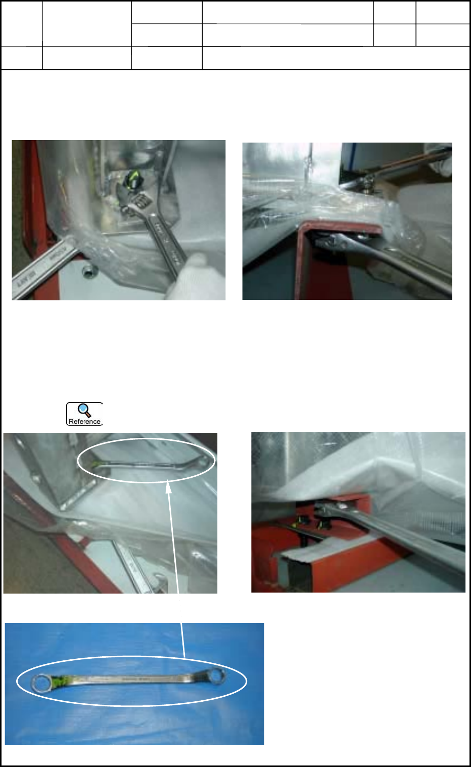
(1) Remove the anchor bolt located on the front side of the machine.
Lock the head of the anchor bolt as shown in Fig. R14 and turn the nut (located below
the metal fixture) to remove.
Fig. R14
(2) Remove the anchor bolt on the rear side of the machine.
Lock the head of the anchor bolt as shown in Fig. R15 and turn the nut (located below
the metal fixture) to remove.
The head can be locked easily with a ring wrench.
Fig. R15
Top View
Side View
Top View
Side View
Ring Wrench
18-15
0512-001
Device
Name
Chip Mounter
Block Name
Page No.
Unit Name
Revision
Model Item GXH-1
Chapter 18 Packaging
2. Packaging Procedure
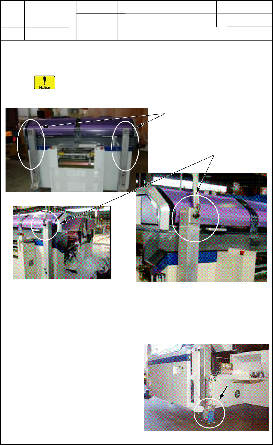
(3) Take out the machine.
• When a crane is used, make use of the four lifting lugs to lift the main body.
Be sure to use a joiner to connect a chain or a wire with the lifting lug.
The length of the chain or the wire shall be such length that will not cause the
chain or the wire at full tension to touch the machine
Fig. R16
• When a forklift is used, insert the forks (platform) from the front side of the machine
so that they will not touch the adjust bolts located at the lower area of the machine
and lift the machine.
(4) While the machine is being lifted up,
attach a special caster (4 pcs. in total)
to the lower area of each lifting lug.
Fig. R17
Lifting Lugs
Joiners
Connection of Chain or Wire with Lifting Lug
18-16
0512-001