SM-131-006.pdf - 第81页
Device Name Chip Mounter Block Name Page No. Unit Name Revision Model Item GXH-1 Chapter 3 Various Setting 2. Setting of Various Boards 2.9 Setting of Multiaxis Driver Boards • Eight pieces of multiaxis driver boards are…
Device
Name
Chip Mounter
Block Name
Page No.
Unit Name
Revision
Model ItemGXH-1
Chapter 3 Various Setting
2. Setting of Various Boards
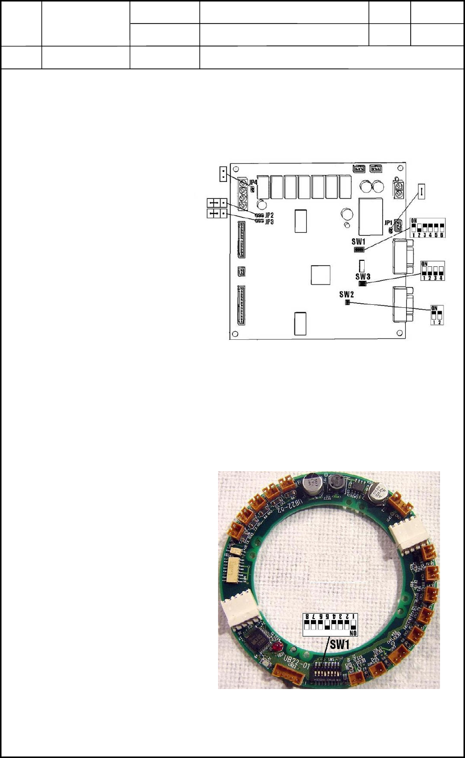
2.7 Setting of UA53 Boards (I/F Boards)
• Two UA53 boards are used in the machine.
Refer to "9. Layout of Various Boards" in chapter 13 for where they are arranged.
2.7.1 Setting of Dip Switches
Set Dip Switches SW1, SW2,
and SW3 as shown in Fig. C7.
2.7.2 Setting of Jumpers
Set Jumpers JP1, JP2, JP3, and
JP4 as shown in Fig. C7.
2.8 Setting of UB22 Board (I/O Board)
• The UB22 board is used in the head section.
Refer to "8. Layout of Head Section" in Chapter 13 for where it is arranged.
2.8.1 Setting of Dip Switch
Set Dip Switch SW1 as shown in
Fig. C8.
Fig. C7 UB53
Fig. C8 UB22
0406-001
3-5

Device
Name
Chip Mounter
Block Name
Page No.
Unit Name
Revision
Model ItemGXH-1
Chapter 3 Various Setting
2. Setting of Various Boards
2.9 Setting of Multiaxis Driver Boards
• Eight pieces of multiaxis driver boards are used in the head and transfer sections.
Refer to "8. Layout of Head Section", "1.5 Layout of BL Block", and "1.6 Layout of
BR Block" in Chapter 13 for the location.
2.9.1 Setting of Boards
When the multiaxis driver boards are
used in the transfer or the head section,
CS1 and SW1 must be set as shown in
Fig. C9.
2.10 Setting of Motion Control Boards
• The motion control boards are used in the CPU2 box.
Refer to "1.8 Layout of FB Block" in Chapter 13 for the location.
2.10.1 Setting of Dip Switches
Set Dip Switch SW1 of the U82, U83, and U84 boards as shown in Fig. C10.
Fig. C9 Setting of Switch for Multiaxis
Driver Board
Fig. C10 Dip Switches of Motion Control Boards
0406-001
3-6
Device
Name
Chip Mounter
Block Name
Page No.
Unit Name
Revision
Model ItemGXH-1
Chapter 3 Various Setting
2. Setting of Various Boards
2.11 Setting of HLS Center Board
• The HLS center board is used in the CPU2 box.
Refer to "1.8 Layout of FB Block" in Chapter 13 for the location.
2.11.1 Setting of Dip Switch
Set Dip Switch SW1 as shown in Fig. C11.
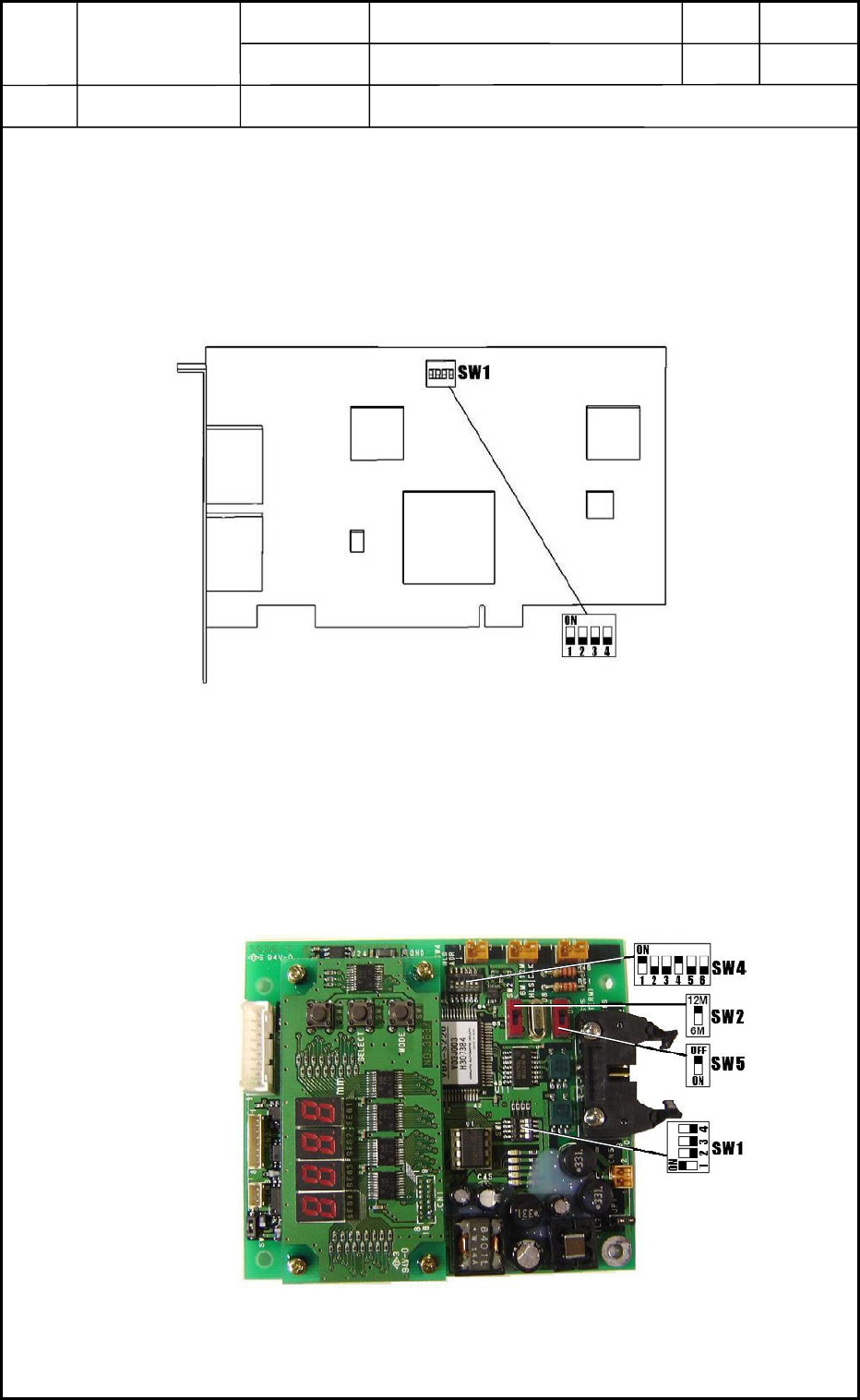
2.12 Setting of Linear Measure Sensor Control Board
• The linear measure sensor control board is used in the head section.
Refer to "7. Layout of Beam Section" in Chapter 13 for the location.
2.12.1 Setting of Dip Switches
Set Dip Switches SW1, SW2, SW4, and SW5 as shown in Fig. C12.
Fig. C11 Dip Switch of HLS Center Board
Fig. C12 Dip Switches of Linear Measure Sensor
Control Board
0406-001
3-7