SM-131-006.pdf - 第178页
Device Name Chip Mounter Block Name Page No. Unit Name Revision Model Item GXH-1 Chapter 8 Component Supply 3. Replacement of Feeder Connector 3.1 Detachment of Feeder Connector (1) Pull out the feeder set from the main …
Device
Name
Chip Mounter
Block Name
Page No.
Unit Name
Revision
Model ItemGXH-1
Chapter 8 Component Supply
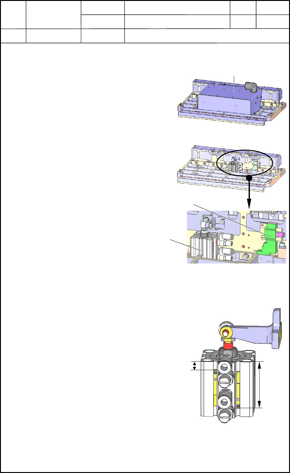
2. Replacement of Cylinder and Valve for Feeder Clamping
2.1 Detachment of Cylinder & Valve for Feeder Clamping
(1) Pull out the cart from the machine.
Refer to the instruction manual for how to
pull out the cart.
(2) Place the feeder base on the work bench as
shown in Fig. H13.
(3) Open the electrical box to expose the
contents as shown in Fig. H14.
(4) The cylinder and valve become visible as
shown in Fig. H15. Pull out the connector
and the hose from them and detach the
main body.
2.2 Attachment of Cylinder & Valve for Feeder Clamping
(1) Attach the proximity sensor of the cylinder
as shown in Fig. H16.
(2) Follow the reverse order of detachment to
attach the cylinder and the valve.
0406-001
8-4
Fig. H13
Electrical Box
Fig. H14
Valve
Fig. H15 Magnified View
Cylinder
18.0±0.5 mm
34.0±0.5 mm
Fig. H16
Device
Name
Chip Mounter
Block Name
Page No.
Unit Name
Revision
Model ItemGXH-1
Chapter 8 Component Supply
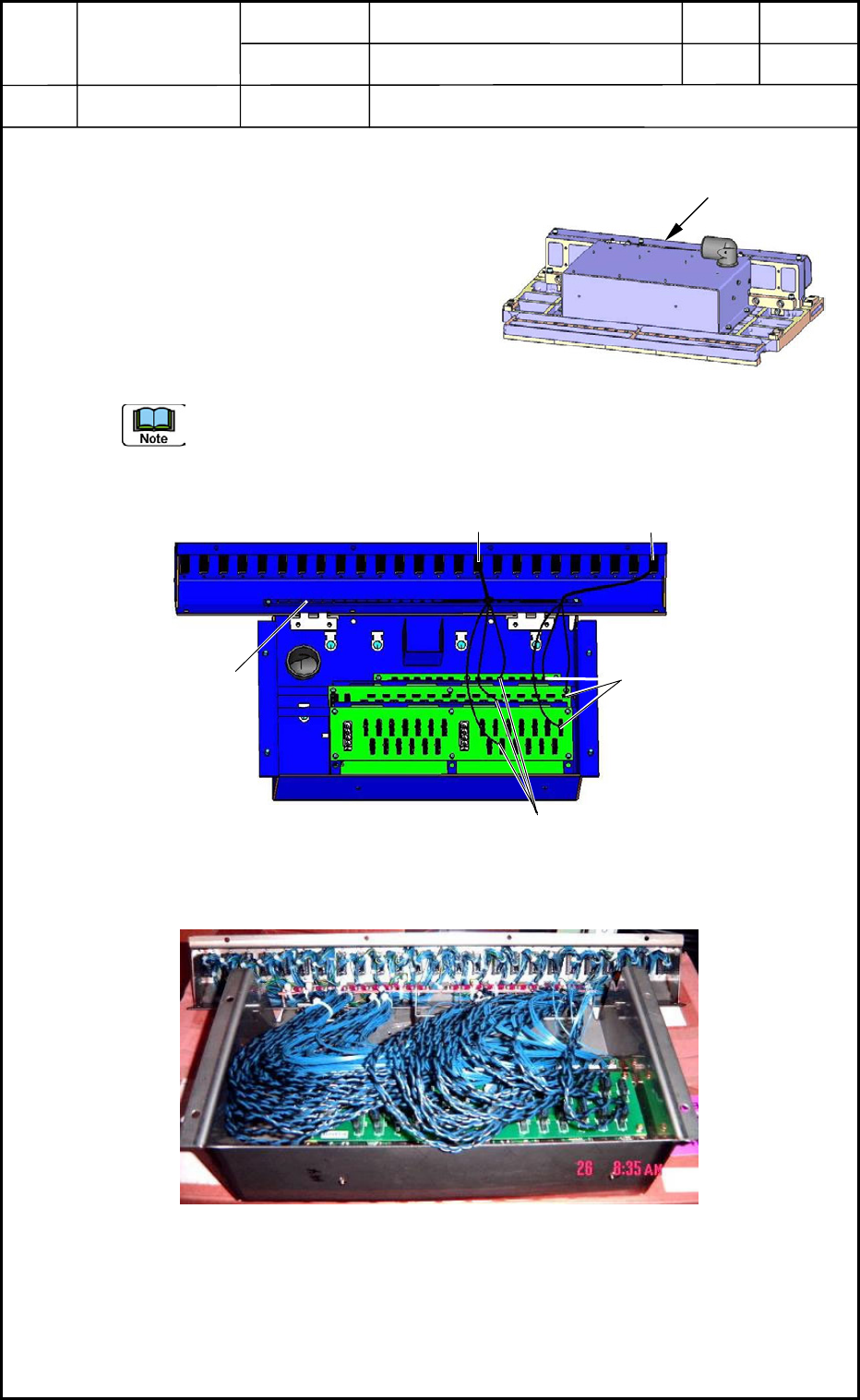
3. Replacement of Feeder Connector
3.1 Detachment of Feeder Connector
(1) Pull out the feeder set from the main
machine.
(2) Place the feeder base on the work bench as
shown in Fig. H15.
(3) Open the electrical box and place it on the
work bench as shown in Fig. H16.
(4) Pull out the connector on the PCB side and
detach the object connector.
(a) The connector No. on the PCB side and the connector No. of the feeder are
identical as shown in Fig. H16.
(b) It may be necessary to detach the PCB.
0406-001
8-5
Fig. H15 Feeder Base
Electrical Box
#1 Connector
#10 Connector
CN10 for Each Other
Fig. H16 Wiring-1 in Electrical Box
Fixing Area for Grounding
CN1 for Each Other
Fig. H17 Wiring-2 in Electrical Box

Device
Name
Chip Mounter
Block Name
Page No.
Unit Name
Revision
Model ItemGXH-1
Chapter 8 Component Supply
3. Replacement of Feeder Connector
3.2 Attachment of Feeder Connectors
(1) Follow the reverse order of detachment to attach a new connectors to the electrical box.
(a) Fix the grounding wire of each connector to the fixing area for grounding.
(Fig. H16)
(b) Check to see that no wires are trapped (pinched) and no air hoses are bent after
the connection.
(2) Place the feeder base on the feeder cart and insert the cart into the main machine.
After that, check the performance.
• Check the upward and downward movement of the feeder base.
• Check the clamping of the feeders.
• Check that the power is supplied to the feeders.
0406-001
8-6