SM-131-006.pdf - 第185页
0406-001 9- B

Chapter 9
Cutter Section
This chapter describes how to replace and adjust the cutter
section.
• Replacement of Cutter Blades
• Replacement of Cutter Axis Motor
• Replacement of Cutter Axis Servomotor Amplifiers
• Location of Limit Sensors
• Belt Tension
0406-001 9-A

0406-001 9-B
Device
Name
Chip Mounter
Block Name
Page No.
Unit Name
Revision
Model ItemGXH-1
Chapter 9 Cutter Section
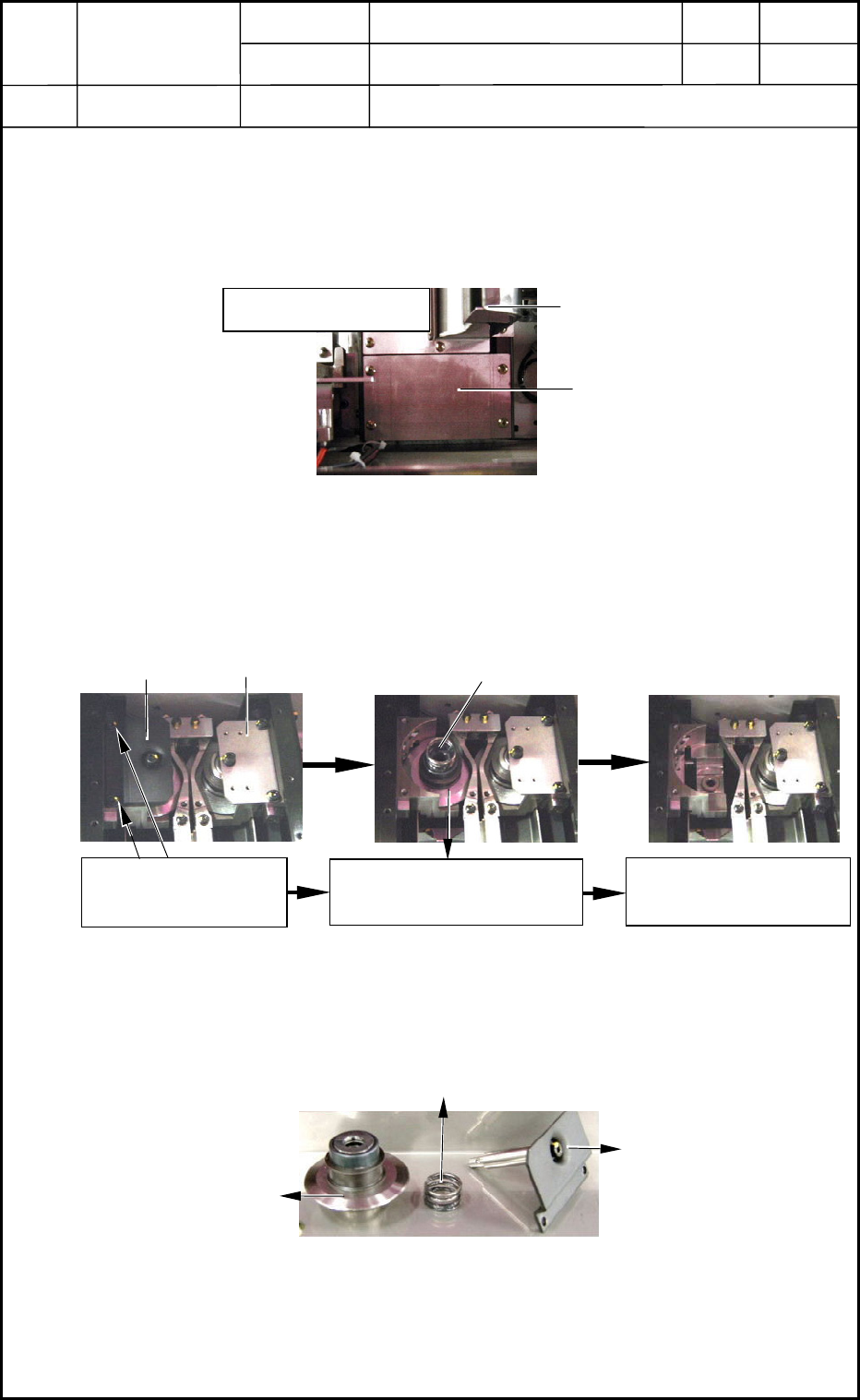
1. Replacement of Cutter Blades
1.1 Preparation before Work on Cutter Blades
(1) Zero the cutter and shut down the power supply to the machine.
(2) Open the door and detach the cover for the cutter blade replacement in Fig. I1 from the
side face of the machine.
1.2 Detachment of Cutter Blades
Follow the steps in Fig. I2 to detach the upper blade.
(The same steps must be followed to detach the lower blade.)
1.3 Attachment of Cutter Blade
(1) Follow the reverse order of detachment to attach the cutter blade as shown in Fig. I3.
(2) Reset the machine to the original condition. Now, the work is completed.
0406-001
9-1
Tape Guide
Cover for Cutter Blade
Replacement
Fig. I1 Cutter Section in Stage #1 or #4
From the upper area
(1) Remove the anchor
bolt.
(2) Take out the upper blade
unit by hand.
(3) Now, the detachment
is completed.
Upper Blade Unit Section
Fig. I2 Detachment of Cutter Blade
Upper Blade Suppression Spring
Lower Blade Unit
Upper Blade Suppression Spring
Upper Blade
Suppression Cover
& Upper Blade Axis
Upper Blade
Fig. I3 Cutter Upper Blade Unit Section