SM-131-006.pdf - 第107页
Device Name Chip Mounter Block Name Page No. Unit Name Revision Model Item GXH -1 2. Replacement of Linear Measure Sensor Chapter 5 Head Section Linear Measure Sensor 2.4 Adjustment of Li near Measure Sensor (1) Detach t…
Device
Name
Chip Mounter
Block Name
Page No.
Unit Name
Revision
Model ItemGXH-1
2. Replacement of Linear Measure Sensor
Chapter 5 Head Section
Linear Measure Sensor
2.2 Attachment of Linear Measure Sensor
2.2.1 Attachment of Linear Measure Sensor on Light Emitting Side
Follow the reverse order of the steps described in "2.1 Detachment of Linear Measure
Sensors". When the linear measure sensor on the light emitting side is attached, be careful not
to make the bundled connector wires trapped (pinched).
2.2.2 Attachment of Linear Measure Sensors on Light Emitting and
Receiving Sides
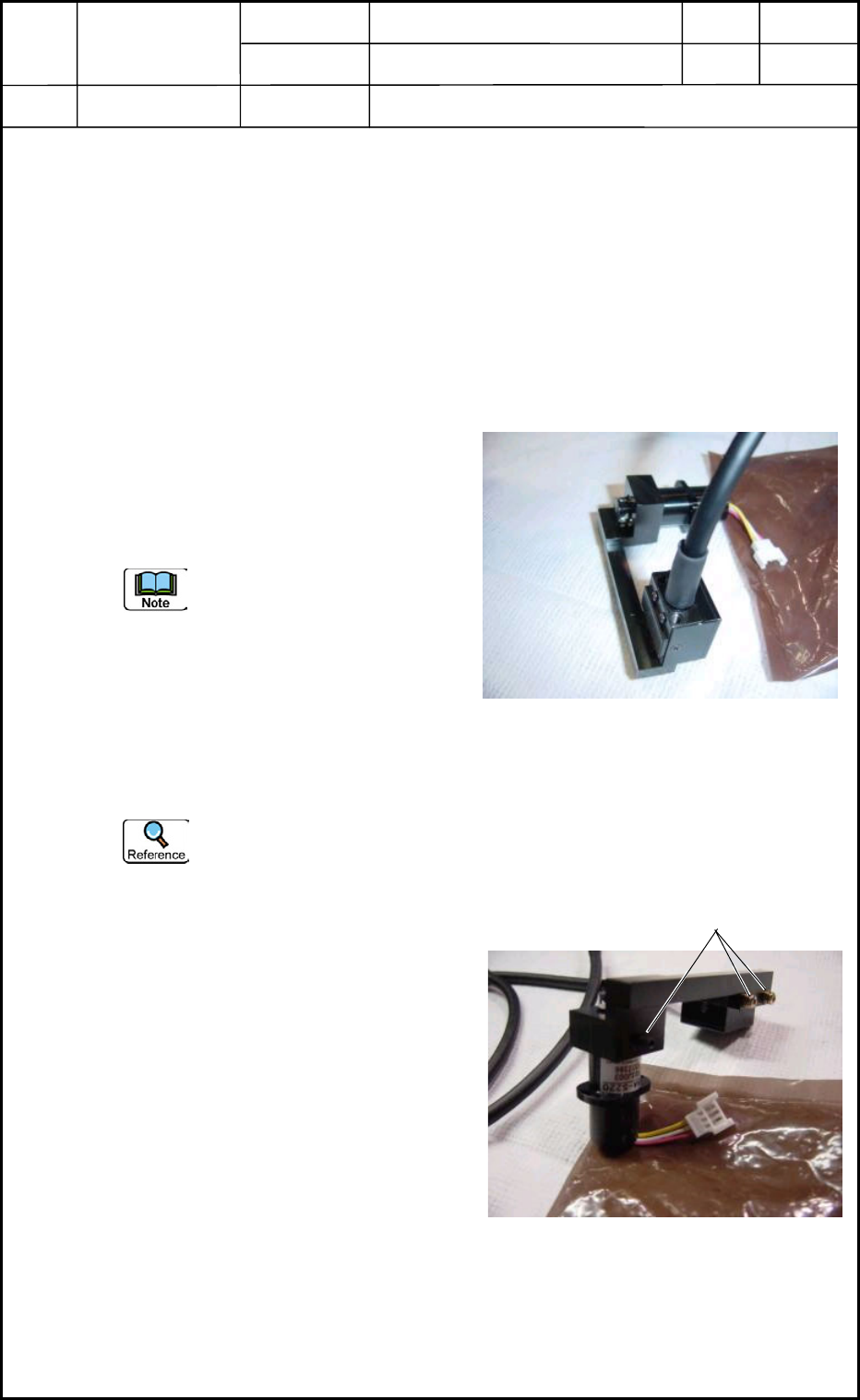
(1) A mounting jig is attached as shown in
Fig. E9 (the condition at the purchase).
Attach the linear measure sensor to the
DD motor side under this condition.
(a) Before the attachment, be
sure not to detach the sensor
from the mounting jig nor
loosen the bolts.
(b) Do not make the glass side
dirty.
Be sure not to make the wires trapped (pinched).
Light Emitting Side: M1.6L5 (2 pcs.)
Light Receiving Side: M3L8 sw and small fw (2 pcs.)
(2) After the linear measure sensor has been
attached, detach the mounting jig. (Fig.
E10)
(3) Attach the linear measure sensor
amplifier board.
(4) Connect the wires in the head section.
Re-bundle the wires on the light
receiving side and the wires running up
to the linear measure sensor amplifier
board.
2.3 Adjustment of Offsets
(1) Master Nozzle Level Offset (Offset: 0.5±0.1 mm)
(2) Nozzle Level Offset
Fig. E9 Mounting Jig
Remove these screws.
Fig. E10
0406-001
5-5
Device
Name
Chip Mounter
Block Name
Page No.
Unit Name
Revision
Model Item GXH-1
2. Replacement of Linear Measure Sensor
Chapter 5 Head Section
Linear Measure Sensor
2.4 Adjustment of Linear Measure Sensor
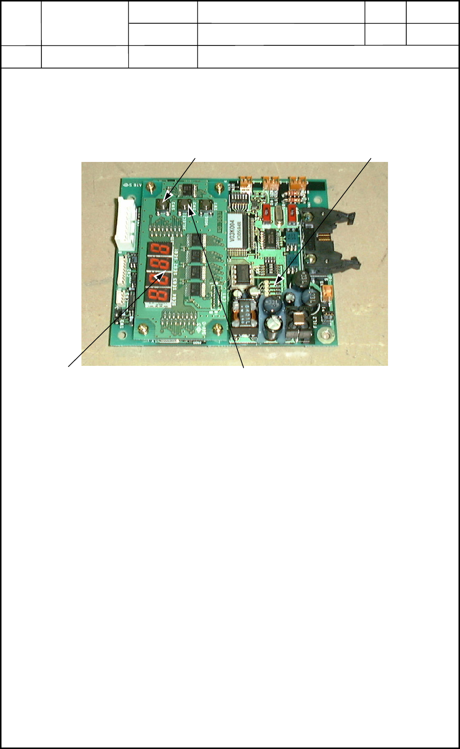
(1) Detach the cover of the amplifier for the linear measure sensor to make the amplifier
(PCB) visible as shown in Fig. E10-2.
Mode Lamp
Power Supply : Lowest LED
Power ON with LED ON (Green)
Continuous Measurement : Second One from Top
Continuous Measurement ON with LED ON
(Real-Time Display)
Max. Value Measurement : Second One from Top
Max. Value Measurement ON with LED ON
(Automatic Operation = Max. Value Measurement)
Optical Axis Check : LED ON (4 pcs.) (Orange)
0602-002
5-6
[MODE] Switch (SW3)
[Measurement Mode] Switch (SW2)
"Max. Value/Continuous Measurement"
Selection Button
Mode Lamp
7-Segment Display
(E/NR Value Indicator) (Data Display)
E/NR: Light Emitted and Not Received
Fig. E10-2
Device
Name
Chip Mounter
Block Name
Page No.
Unit Name
Revision
Model ItemGXH-1
2. Replacement of Linear Measure Sensor
Chapter 5 Head Section
Linear Measure Sensor
(2) Check for dirt, nicks, and scratches.
(2.1) Set the amplifier in the "Real-Time Display" mode.
(2.2) Press the [Measurement Mode] switch (SW2).
• Mode Lamp ON (Fig. E10-2)
(2.3) Rotate the head by hand without any nozzles on it.
• When nothing is displayed on the amplifier (7-segment display), proceed to
Step (3).
• When a numerical value is displayed on the amplifier (7-segment display),
follow the steps below.
Clean the light emitting and receiving surfaces of the linear measure sensor
with a cotton swab soaked in denatured ethanol and wipe them dry with another
cotton swab. (Repeat the steps again, starting with Step (2.1).)
When data on any one of the twelve nozzles is still displayed after the surfaces
are cleaned several times, it is required to replace the set of amplifier and sensor
with a new one.
(3) Check the height.
(3.1) Attach the No. 1 master nozzle to the nozzle holder and make a measurement in
the "Real-Time Display" mode.
(3.2) Rotate the DD motor (head rotational axis) and adjust it to the point where the
maximum E/NR value of the linear measure sensor can be displayed.
At this time, confirm that the NS axis (nozzle selection axis) is directed toward
the camera side.
The axis can be rotated by hand for the adjustment with the servomotor being
turned OFF.
• When the result of the measurement meets the specified value or less (0.5±0.1
mm), proceed to Step (4).
• When the result is out of the specified range, follow the steps below.
Only the height adjustment of the light receiver side (square sensor) is required.
Loosen the screw and adjust the height for 0.5±0.1 mm while checking the 7-
segment display to keep the sensor horizontal.
At this time, this sensor should not be located below the lower surface of the
light emitter (round sensor). (Design Value: 0.2 mm higher)
(3.3) Set the amplifier in the "Max. Measurement Display" mode.
0406-001
5-7