SM-131-006.pdf - 第153页
Device Name Chip Mounter Block Name Page No. Unit Name Revision Model Item GXH-1 Chapter 6 Backup Base Section 1. Replacement of Backup Base Motor Motor Bracket 4 250 Fig. F3 Belt Tension Timin g Pulle y S20 1.3 Backup U…

Device
Name
Chip Mounter
Block Name
Page No.
Unit Name
Revision
Model ItemGXH-1
Chapter 6 Backup Base Section
1. Replacement of Backup Base Motor
1.1 Tightening Torque and Mounting Dimension for Backup U/D
Motor and Mechanical Lock
(1) Attach Plate 4 to Motor S23 with two bolts
with hexagon holes (M4L10), SW, and FW.
(2) Attach Mechanical Lock S22 and Pulley
S19 to the shaft of Motor S23.
At this time, confirm that the
tightening torque of the mechanical
lock is "250 kgf/cm" when the
dimension between the motor
mounting face and the bottom surface
of the pulley is "11.5 to 12.0 mm".
1.2 Confirmation of Height and Parallelism for Upper Surface of
Spline Shaft at Phase C Detection
(1) Connect the jig, release the brake, rotate the motor by hand, and detect Phase C. At
the detection position, turn the brake "ON".
(2) Regard the upper surface of Spline Shaft S16 as a reference and confirm with digital
height and dial gauges that the height of the shaft's upper surface is "232.0±0.2 mm"
from the lower surface of Base 1 and the parallelism of Points A, B, C, and D on the
shaft is "0.1 mm or less".
(3) Adjust the intermesh of Timing Pulley S20 with the belt and temporarily set up the
height of Timing Pulley S20.
232.0±0.2 mm
Block
A
B
D
C
Phase C Detected
Spline Shaft S16
Fi
g
. F2 Phase C and S
p
line Hei
g
ht
Base 1
Plate 4
Motor S23
11.5 to 12.0
(3)
Pulley S19
Mechanical
Lock S22
Fig. F1 Motor
0406-001
6-1
Device
Name
Chip Mounter
Block Name
Page No.
Unit Name
Revision
Model ItemGXH-1
Chapter 6 Backup Base Section
1. Replacement of Backup Base Motor
Motor Bracket 4
250
Fig. F3 Belt Tension
Timin
g
Pulle
y
S20
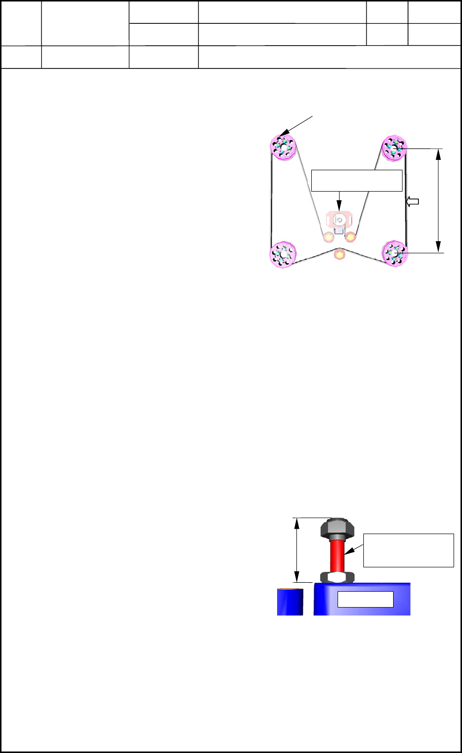
1.3 Backup U/D and Timing Belt
Measure the arrow-marked position with
a digital tensometer and confirm that the
tension becomes "59 to 69 N (6.0 to 7.0
kgf)".
• When the measured tension value
differs from the specified one, adjust
the tension with Motor Bracket 4.
(Rotate the pulley and measure
several spots. Connect the jig and
release the brake.)
Set Value for Tensometer:
Width = 12 mm
Unit Weight = 0.25 gf/cm
2
Span = 250 mm
1.4 Leveling of Ball Spline
While keeping the motor braked and Phase C detected, use the slot (Timing Pulley S20) to
adjust the dimension (the distance up to the upper surface of Spline Shaft S16) for
"232.0±0.2 mm" and the parallelism of Points A, B, C, and D on the shaft for "0.01 mm or
less".
1.5 Setting Confirmation of Lower Limit Mechanical Stopper
Attach Lower Limit Mechanical Stopper
S29 to Base 1.
At this time, the dimension between the
stopper mounting face of the base and the
stopper rubber end must be "36.0 mm (35.5
to 36.0 mm).
35.5 to 36.0
Mechanical
Stopper S29
Base 1
Fi
g
. F4 Sto
pp
er Bolt
0406-001
6-2
Device
Name
Chip Mounter
Block Name
Page No.
Unit Name
Revision
Model ItemGXH-1
Chapter 6 Backup Base Section
1. Replacement of Backup Base Motor
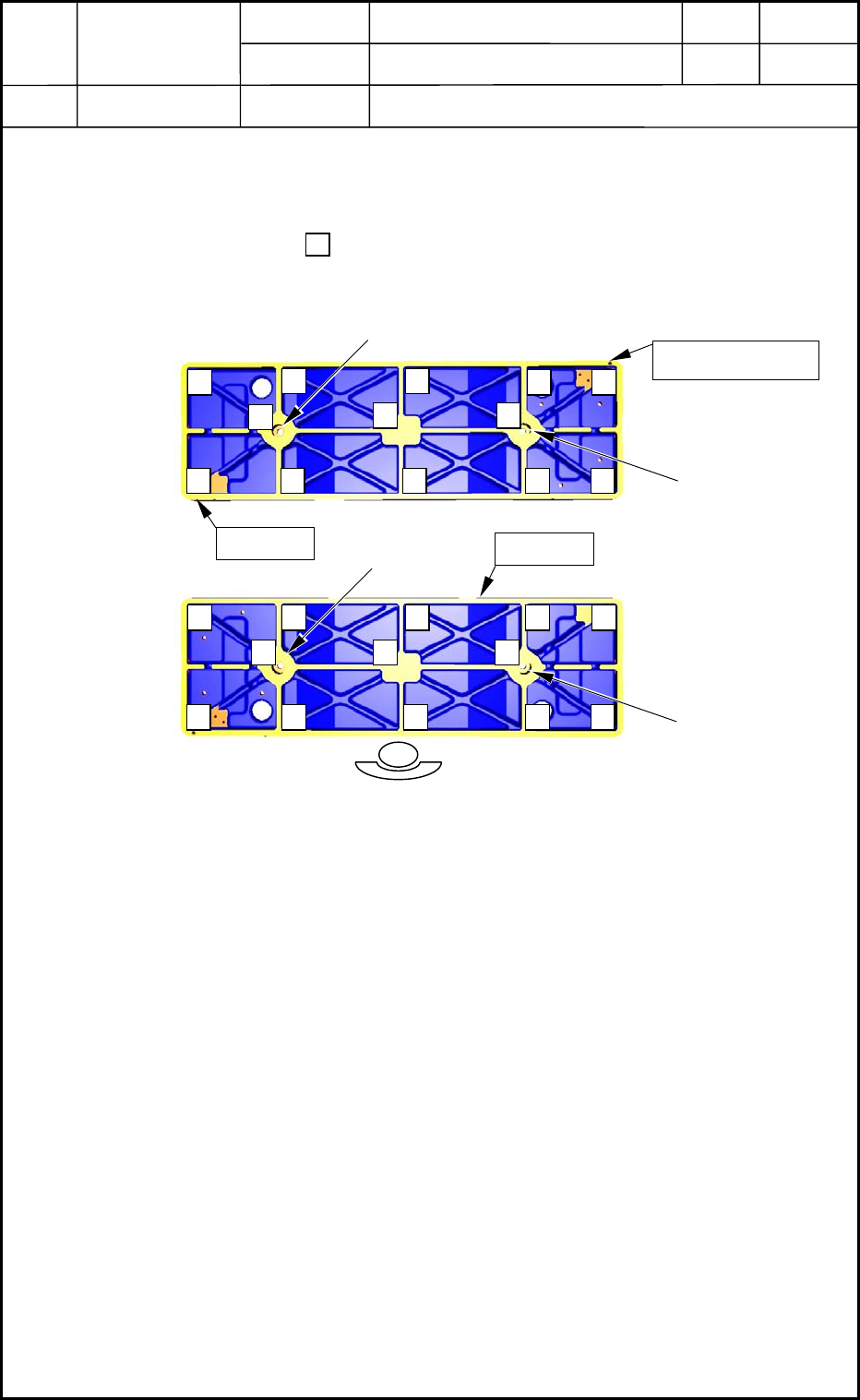
1.6 Flatness Confirmation of Backup Base
(1) Fix the backup base with the bolts (M6L16), SW, and FW so that the positioning pin
can be located outside.
(2) Apply a dial gauge to in Bases a and b and confirm that the total flatness of a and
b is "0.1 mm or less".
Base a
Base b
Positioning Pin
M6L16
M6L16
M6L16
M6L16
Fig. F5 Flatness of Backup Base
0406-001
6-3