SM-131-006.pdf - 第79页
Device Name Chip Mounter Block Name Page No. Unit Name Revision Model Item GXH-1 Chapter 3 Various Setting 2. Setting of Various Boards 2.5 Setting of UB14 Boards (I/O Boards) • The UB14 boards are used at three places -…
Device
Name
Chip Mounter
Block Name
Page No.
Unit Name
Revision
Model ItemGXH-1
Chapter 3 Various Setting
2. Setting of Various Boards
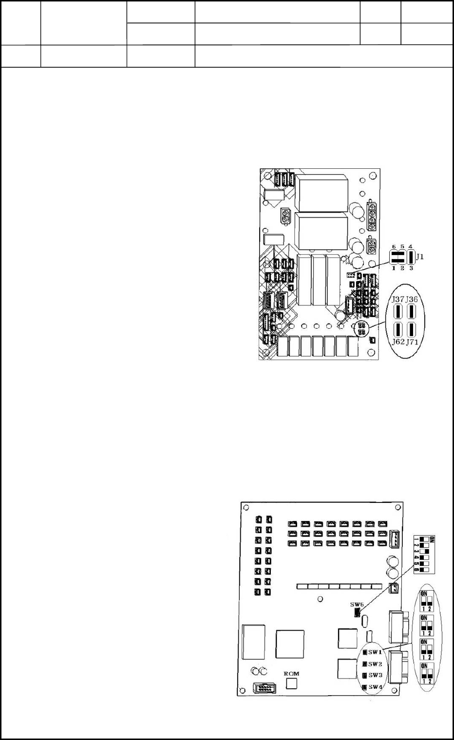
2.3 Setting of UB21 Boards (Relay Boards 2)
• Two pieces of UB21 boards are used in the power supply section.
Refer to "1.5 Layout of BL Block" and "1.6 Layout of BR Block" in Chapter 13 for
the location.
2.3.1 Setting of Jumper Wires
Set Jumper Wires J1, J36, J37, J62, and
J71 as shown in Fig. C3.
2.4 Setting of UA54 Boards (ILB Boards)
• Two pieces of UA54 boards are used in the power supply section.
Refer to "1.5 Layout of BL Block" and "1.6 Layout of BR Block" in Chapter 13 for
the location.
2.4.1 Setting of Dip Switches
Set Dip Switches SW1, SW2, SW3,
SW4, and SW5 as shown in Fig. C4.
2.4.2 ROM Mounting
Mount ROM as shown in Fig. C4.
Fig. C3 UB21
Fig. C4 UA54
0406-001
3-3
Device
Name
Chip Mounter
Block Name
Page No.
Unit Name
Revision
Model ItemGXH-1
Chapter 3 Various Setting
2. Setting of Various Boards
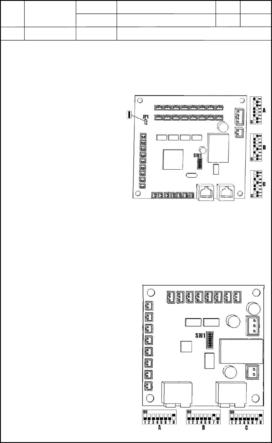
2.5 Setting of UB14 Boards (I/O Boards)
• The UB14 boards are used at three places - Power Supply Section, Transfer
Section, and Cutter/Positioning Section.
Refer to "9. Layout of Various Boards" in chapter 13 for where they are arranged.
2.5.1 Setting of Dip Switches
• When the UB14 board is used in
the power supply section, set
SW1 like "A" in Fig. C5.
• When the UB14 board is
used in the transfer section,
set SW1 like "B" in Fig. C5.
• When the UB14 board is
used in the cutter/positioning
section, set SW1 like "C" in
Fig. C5.
2.5.2 Setting of Jumper
With Jumper JP1, short between two pins as shown in Fig. C5.
2.6 Setting of UB13 Boards (I/O Boards)
• The UB13 boards are used at three places - Front Operation Panel, Rear
Operation Panel, and Light Tower.
Refer to "9. Layout of Various Boards" in chapter 13 for where they are arranged.
2.6.1 Setting of Dip Switches
• When the UB13 board is used in
the front operation panel, set
SW1 like "A" in Fig. C6.
• When the UB13 board is used in
the rear operation panel, set SW1
like "C" in Fig. C6.
• When the UB13 board is used in
the light tower, set SW1 like "B"
in Fig. C6.
Fig. C5 UB14
Fig. C6 UB13
0406-001
3-4
Device
Name
Chip Mounter
Block Name
Page No.
Unit Name
Revision
Model ItemGXH-1
Chapter 3 Various Setting
2. Setting of Various Boards
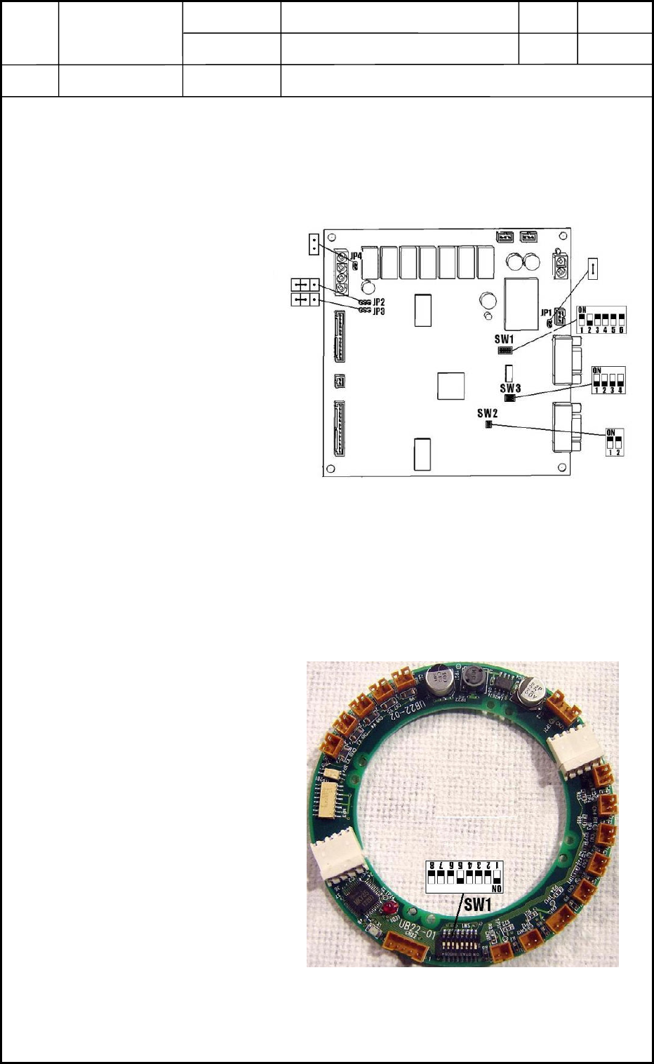
2.7 Setting of UA53 Boards (I/F Boards)
• Two UA53 boards are used in the machine.
Refer to "9. Layout of Various Boards" in chapter 13 for where they are arranged.
2.7.1 Setting of Dip Switches
Set Dip Switches SW1, SW2,
and SW3 as shown in Fig. C7.
2.7.2 Setting of Jumpers
Set Jumpers JP1, JP2, JP3, and
JP4 as shown in Fig. C7.
2.8 Setting of UB22 Board (I/O Board)
• The UB22 board is used in the head section.
Refer to "8. Layout of Head Section" in Chapter 13 for where it is arranged.
2.8.1 Setting of Dip Switch
Set Dip Switch SW1 as shown in
Fig. C8.
Fig. C7 UB53
Fig. C8 UB22
0406-001
3-5