SM-131-006.pdf - 第127页
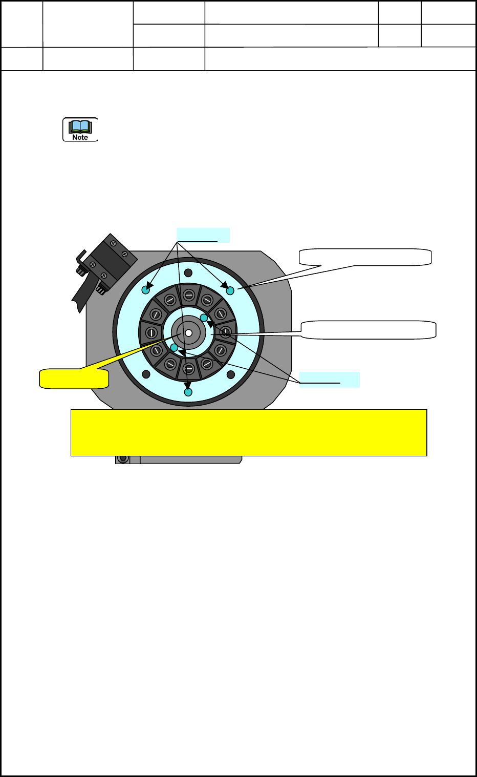
Device Name Chip Mounter Block Name Page No. Unit Name Revision Model Item GXH -1 Chapter 5 Head Section 7. MSB W hole Cleaning and Lubricat ion Procedures View of Head Bottom Surface 1 12 11 10 9 8 7 6 5 4 3 2 M1.6×L4 L…
Device
Name
Chip Mounter
Block Name
Page No.
Unit Name
Revision
Model Item GXH-1
Chapter 5 Head Section
7. MSB Whole Cleaning and Lubrication Procedures
(7) Detach the large and small diffusion plates. (See Fig. E51 below)
(Large: 3-M1.6×L4 Bolts, Small: 2-M1.6×L4)
There might have been cases where the screw lock (Three Bond 1401B) applied last time
has protruded to the bolt fixing section and adhered to the attaching surface of the
diffusion plates. In this case, please be careful not to force the diffusion plates to detach
because it will cause damages of diffusion plates and the screw lock adhered on the
surface
must be removed cleanly.
View of Head Bottom Surface
Fig. E51
0605-001
5-25
M1.6×L4
Exercise adequate care in detaching the small diffusion plate not to
damage. Especially, we recommend applying a wrench to the transparent
section of the light emission section tip side surface or covering the section
with
p
lastic wra
p
to
p
rotect.
! Caution
Large Diffusion Plate
Small Diffusion Plate
M1.6×L4
Device
Name
Chip Mounter
Block Name
Page No.
Unit Name
Revision
Model Item GXH-1
Chapter 5 Head Section
7. MSB Whole Cleaning and Lubrication Procedures
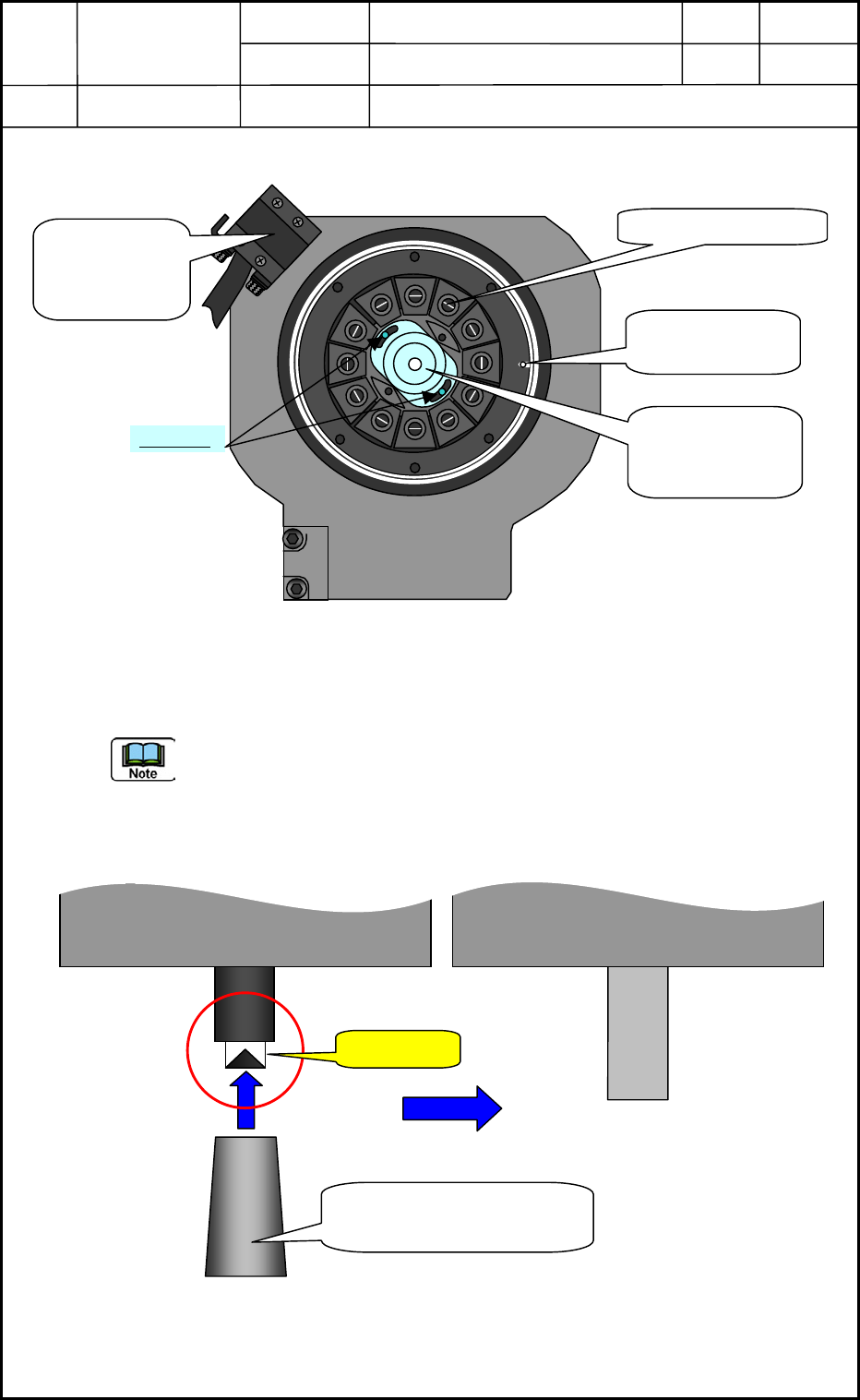
View of Head Bottom Surface
1
12
11
10
9
8
7
6
5
4
3
2
M1.6×L4
Linear Measure
Sensor Light
Receiving side
Linear Measure
Sensor Light
Emission side
No.1 Nozzle Position
Locating Pin
(Origin Position)
(8) Detach the linear measure sensor light emission side. (2-M1.6×L4 bolts)
Fig. E52
Apply a wrench or something tool to the transparent section located to the edge side of
the light emission section and remove the 2-M1.6×L4 hexagon head bolts but in this case,
surely put the protection tube (cover) on the linear measure sensor to protect from
damages
before this operation. (See Fig. E53 below)
Fig. E53
0605-001
5-26
Protection Tube (cover) for
Linear measure Sensor
! Caution
Head Side View
Device
Name
Chip Mounter
Block Name
Page No.
Unit Name
Revision
Model Item GXH-1
Chapter 5 Head Section
7. MSB Whole Cleaning and Lubrication Procedures
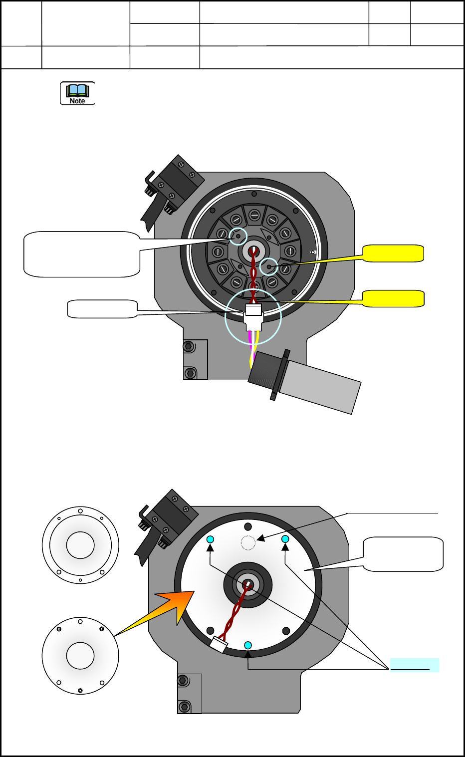
- Tenderly pull out the linear measure sensor in detaching operation and disconnect the
connector.
- Cleanly remove the screw lock (Three Bond 1401B) remained last time that why the
screw lock protruded from the bolt section has adhered to the attaching surface. If
omitting this operation, it may cause some problems such as the height of the linear
measure sensor is different from the setting.
Fig. E54
(9) Attach the head section attaching jig (A lid for protecting nozzle shaft jumping out) to
the head and with using a tap hole for the large diffusion plate as shown in Fig. 55 below.
Fig. E55
View of Head Bottom Surface
No.1 Nozzle
Connector
! Caution
! Caution
Maybe, the screw
lock applied last time
has remained here.
Back Surface
Front Surface
View of Head Bottom Surface
No.1 Nozzle Position
No.1 ノズル
M1.6×L4
Head section
attaching Jig
Back Surface
0605-001
5-27