SM-131-006.pdf - 第109页
Device Name Chip Mounter Block Name Page No. Unit Name Revision Model Item GXH-1 2. Replacement of Linear Measure Sensor Chapter 5 Head Section Linear Measure Sensor (4) Check Modes 1 and 2. (4.1) Rotate the DD motor and…
Device
Name
Chip Mounter
Block Name
Page No.
Unit Name
Revision
Model ItemGXH-1
2. Replacement of Linear Measure Sensor
Chapter 5 Head Section
Linear Measure Sensor
(2) Check for dirt, nicks, and scratches.
(2.1) Set the amplifier in the "Real-Time Display" mode.
(2.2) Press the [Measurement Mode] switch (SW2).
• Mode Lamp ON (Fig. E10-2)
(2.3) Rotate the head by hand without any nozzles on it.
• When nothing is displayed on the amplifier (7-segment display), proceed to
Step (3).
• When a numerical value is displayed on the amplifier (7-segment display),
follow the steps below.
Clean the light emitting and receiving surfaces of the linear measure sensor
with a cotton swab soaked in denatured ethanol and wipe them dry with another
cotton swab. (Repeat the steps again, starting with Step (2.1).)
When data on any one of the twelve nozzles is still displayed after the surfaces
are cleaned several times, it is required to replace the set of amplifier and sensor
with a new one.
(3) Check the height.
(3.1) Attach the No. 1 master nozzle to the nozzle holder and make a measurement in
the "Real-Time Display" mode.
(3.2) Rotate the DD motor (head rotational axis) and adjust it to the point where the
maximum E/NR value of the linear measure sensor can be displayed.
At this time, confirm that the NS axis (nozzle selection axis) is directed toward
the camera side.
The axis can be rotated by hand for the adjustment with the servomotor being
turned OFF.
• When the result of the measurement meets the specified value or less (0.5±0.1
mm), proceed to Step (4).
• When the result is out of the specified range, follow the steps below.
Only the height adjustment of the light receiver side (square sensor) is required.
Loosen the screw and adjust the height for 0.5±0.1 mm while checking the 7-
segment display to keep the sensor horizontal.
At this time, this sensor should not be located below the lower surface of the
light emitter (round sensor). (Design Value: 0.2 mm higher)
(3.3) Set the amplifier in the "Max. Measurement Display" mode.
0406-001
5-7
Device
Name
Chip Mounter
Block Name
Page No.
Unit Name
Revision
Model ItemGXH-1
2. Replacement of Linear Measure Sensor
Chapter 5 Head Section
Linear Measure Sensor
(4) Check Modes 1 and 2.
(4.1) Rotate the DD motor and make the checking at the already adjusted position
(marked position).
At this time, confirm that the NS axis (nozzle selection axis) is directed toward
the camera side.
The axis can be rotated by hand for the adjustment with the servomotor being
turned OFF.
(4.2) Change the mode.
(4.3) Press the [MODE] switch (SW3) to change the mode.
Every time the [MODE] switch is pressed, "Mode 1 (ArA1)", "Mode 2
(ArA2)", "Mode 3 (ArA3)", and "Idling (IdLE)" is set.
• When the checked data stays in the specified range (80 to 120%), proceed to
Step (5).
• Mode 1: less than 80, Mode 2: more than 120
The light receiver (square sensor) should be directed downward. (To reduce the
shape of the wave) (Proceed to Step (3).)
• Mode 1: more than 120, Mode 2: less than 80
The light receiver (square sensor) should be directed upward. (To enlarge the
shape of the wave) (Proceed to Step (3).)
* Target Values: "Mode 1" = 80 to 110%, "Mode 2" = 90 to 120%
(4.4) Set the amplifier back in the "Idling" mode.
(5) Follow the steps below to check the accuracy.
(5.1) Move down the NL axis (nozzle level axis) and check the accuracy.
(5.2) Set the amplifier in the "Real-Time Display" mode.
(5.3) Press the [Measurement Mode] switch (SW2).
• Mode Lamp ON (Fig. E10-2)
(5.4) Attach the master nozzle to the No. 1 nozzle holder.
(5.5) Turn on the servomotor and zero the NL axis (nozzle level axis), the NS axis
(nozzle selection axis), and the DD motor (head rotational axis) in this order.
Do not rotate the DD motor when the NL axis is not zeroed. Otherwise, the
motor will break down.
(5.6) Rotate the DD motor by -45 degrees and make a fine adjustment until the
maximum E/NR value of the linear measure sensor is indicated.
(5.7) Rotate the NS axis by the same degrees as the DD motor.
(5.8) Move down the NL axis by +1,000 µm and +2,000 µm and compare it with the
origin position of the NL axis.
• When the value is ±30 µm or less in comparison with the point around 0.5 mm,
proceed to Step (6).
• When the value is ±30 µm or more in comparison with the point around 0.5 mm,
proceed to Step (3).
(5.9) Set the amplifier in the "Max. Value Measurement" mode.
(Only at the adjustment with the device)
• Only the green LED is turned ON.
(6) Attach the cover of the amplifier for the linear measure sensor.
0406-001
5-8
Device
Name
Chip Mounter
Block Name
Page No.
Unit Name
Revision
Model Item GXH-1
Chapter 5 Head Section
3. Replacement of Doughnut Board
UB22
3.1 Detachment of Doughnut Board
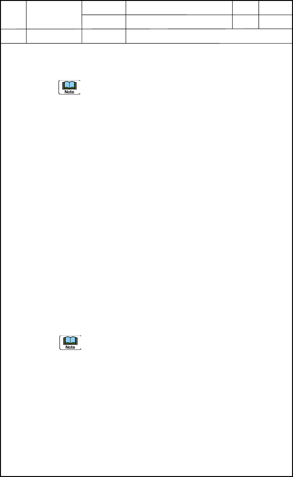
(1) Detach the cover.
Remove the four bolts (M2L6) and detach the transparent cover. (Fig. E12)
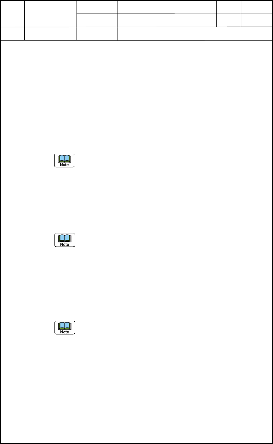
(2) Disconnect Connectors CN1 through
CN12 (Change-Over Valves), CN13,
CN21, and CN22 from the doughnut
board. (Fig. E11)
Be careful not to make the
disconnected connectors
trapped by the frame while the
center shaft is rotating.
(3) Detach the four supports (M2) and
then the board from the motor section
as shown in Fig. E12.
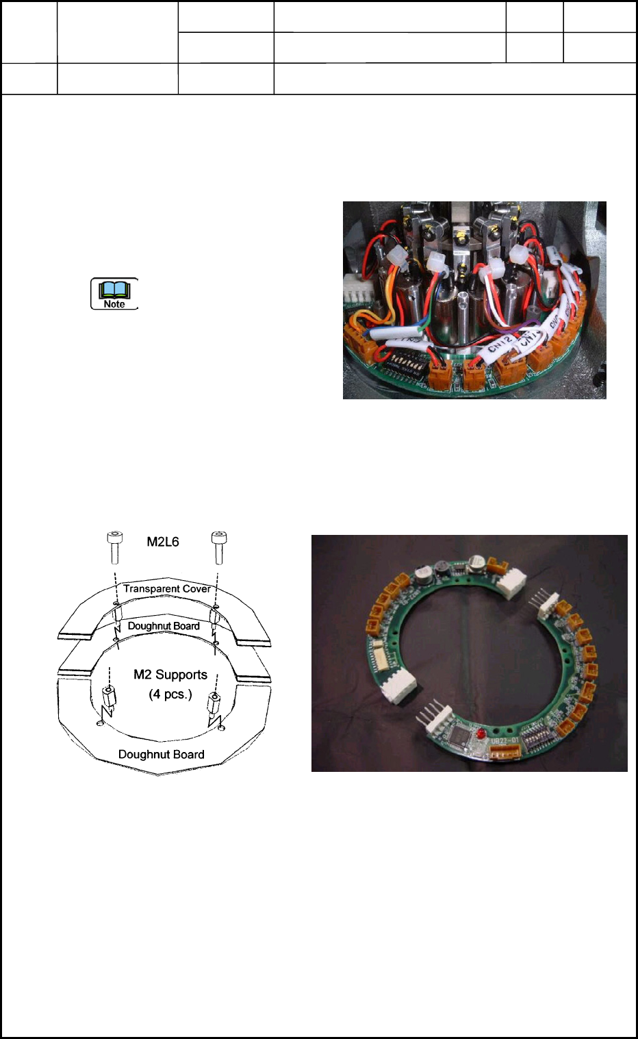
(4) Disconnect the board from the connector sections into two halves as shown in Fig. E13
and take out the board.
Fig. E11 Doughnut Board
Fig. E13 Disconnection of Doughnut Board
Fig. E12 Boards and Cover
0406-001
5-9