SM-131-006.pdf - 第172页
Chapter 8 Component Supply Section This chapter describes how to assemble, replace, and set up the component supply section. • Assembly of Feeder Positioning Section • Replacement of Cylinder and V alve for Feeder Clampi…
Device
Name
Chip Mounter
Block Name
Page No.
Unit Name
Revision
Model ItemGXH-1
Chapter 7 Transfer Section
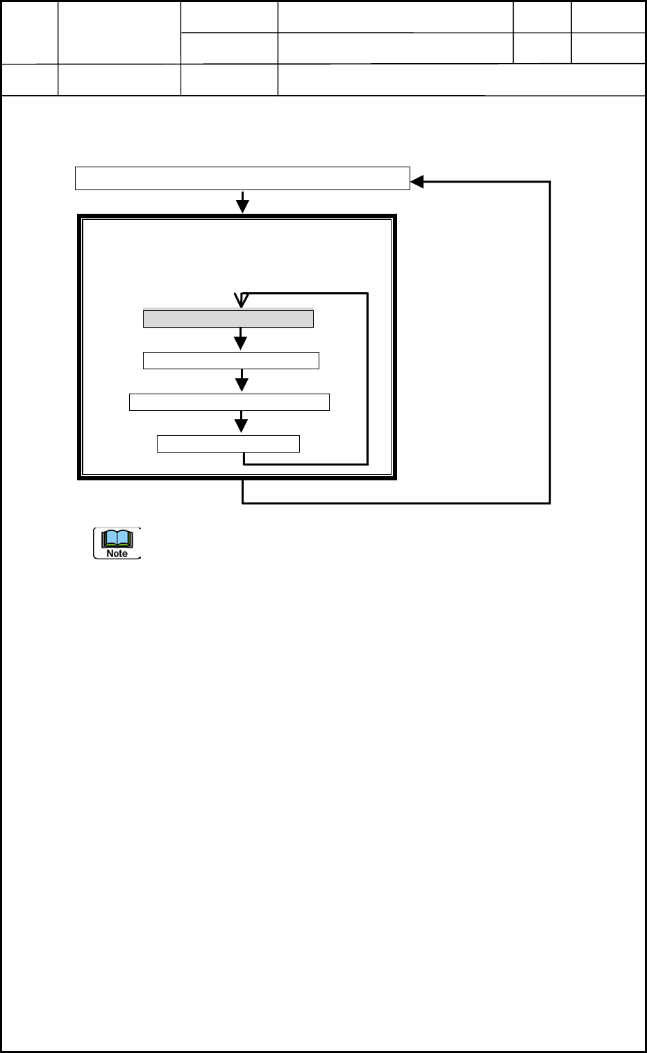
3. Setting of PCB Detection Sensor Amplifiers in NA and NC Sections
(5) Set the timer function.
(Check only if "t0 - Momentary" is set.)
Hold down the D-SW for more than 3 seconds.
Mode Indication: "TMR" ON
Auxiliary Mode Indicator Lamps: ON
When the D-SW is rotated in this mode, the
indication changes as follows.
Momentary (t0 Flickering)
Delay Timer (dt Flickering)
One-Shot Timer (1t Flickering)
Cancel (-- Flickering)
Press the D-SW.
Even after the timer function is changed, the time of the timer is kept as it is.
However, when the timer function is changed from "Momentary Output", the OFF
delay timer output or the one-shot ON timer output is selected.
"TMR" Lamp Flickering in "Mode Selection" Mode
0406-001
7-10

Chapter 8
Component Supply Section
This chapter describes how to assemble, replace, and set
up the component supply section.
• Assembly of Feeder Positioning Section
• Replacement of Cylinder and Valve for Feeder Clamping
• Replacement of Feeder Connector
• Replacement of Batch Connector Cable
• Setting of Lifted Feeder Detection Sensor
0406-001 8-A

0406-001 8-B